
A buyer's guide to planning a campus network fiber optic backbone: site mapping, topology, cable construction, fiber counts, loss budgets, entrance design, testing, phasing, and supplier selection for a 15-year plant.
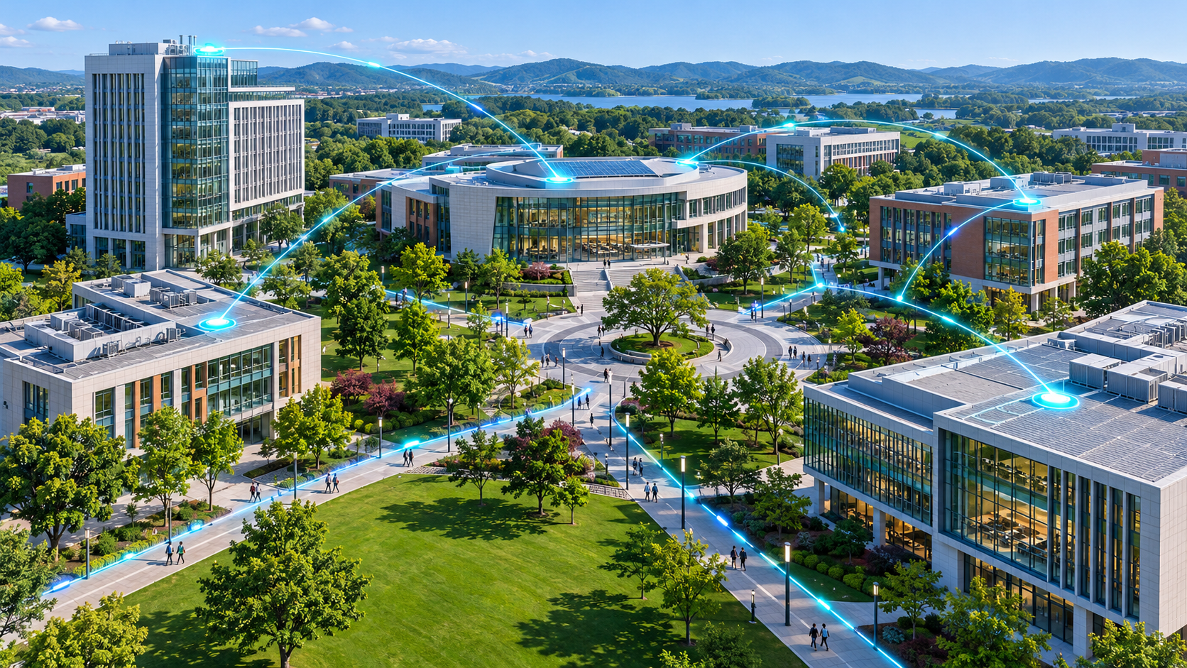
A university campus, a hospital group, a factory park, and a corporate headquarters all share the same physical reality: several buildings, a few hundred meters to a few kilometers apart, that must behave like one network. The cable that binds those buildings together is the campus fiber optic backbone, and it is the single hardest part of the network to change later. Trenches close, ducts fill up, and budgets move on. A backbone planned well on day one quietly carries every future service for ten or fifteen years; a backbone planned carelessly turns every expansion into a construction project.
This guide walks through the planning decisions a B2B buyer, IT manager, or project consultant actually has to make when specifying a campus network fiber optic backbone: mapping the site, choosing a topology, selecting cable types, sizing fiber counts, planning entrances and risers, setting a loss budget, deciding between splicing and pre-termination, testing at handover, and leaving room to grow. Every recommendation reflects typical industry practice; always confirm exact figures against the product datasheet for the cable you order.
1. Why a Campus Backbone Is Not Just "Longer Indoor Cable"
The first mistake in campus planning is treating the backbone as an oversized indoor job. It is not. A campus backbone lives in three different environments at once:
- Outside plant: between buildings, in ducts, trenches, or on poles, exposed to moisture, temperature swings, rodents, and excavation damage.
- Building entrances: where the outdoor cable terminates, transitions, and meets grounding requirements.
- Indoor vertical and horizontal runs: from the entrance room to equipment rooms and floor distributors, subject to fire code and riser/plenum rules.
Each environment has its own cable construction, its own installation discipline, and its own acceptance tests. A cable that is perfect inside a building will fail quickly in a flooded duct; a cable specified for direct burial is wasteful overkill on an indoor tray. Planning a campus backbone means assigning the right construction to each segment and making the transitions deliberate rather than accidental.
There is also a service-life argument. Copper backbone for inter-building links is practically limited to 90–100 m and is vulnerable to ground potential differences between buildings; fiber has neither limit. Optical fiber is dielectric, immune to electromagnetic interference from campus substations, and carries speeds that have multiplied many times over the decades without cable replacement. For most campuses, the question is not whether the backbone should be fiber, but how to specify it.
Cost behavior is the third argument, and it is the one finance officers understand fastest. A copper inter-building link needs repeaters or media converters every hundred meters, each one a powered device that can fail, each one drawing from a different building's UPS. A fiber link spans the whole distance passively: no power, no conversion, no intermediate failure point. Over a fifteen-year horizon, the maintenance hours saved by removing those devices routinely exceed the cable's entire purchase price. When a campus IT team presents a backbone budget, this passive-vs-active comparison is the slide that gets it approved.
2. What "Campus Fiber Optic Backbone" Actually Means
In structured cabling language (the ISO/IEC 11801 and TIA-568 families), the campus backbone is the cabling between the campus main distribution area — usually the central equipment room — and the intermediate distributors in each building. Everything inside a building (risers to floors, horizontal runs to workstations and APs) is separate cabling with separate rules.
Three characteristics define the backbone:
- Reach: typically 300 m to 3 km between buildings, which puts single mode fiber in play for nearly every link.
- Concurrency: the same cable often carries data, VoIP, Wi-Fi uplinks, CCTV, building automation, and access control traffic, which is why the CCTV backbone design and the campus backbone are usually one physical plant.
- Irreversibility: civil works dominate the cost. Pulling extra fibers now costs little; re-trenching later costs a project.
It helps to be precise about what the backbone is not. It is not the internet circuit, though it may carry it. It is not the Wi-Fi, though every access point ultimately rides on it. And it is not the switches — backbone is the passive optical path that lets those switches be placed wherever they are needed. Keeping these layers distinct in your planning documents prevents the common procurement confusion where "backbone" quotes include active equipment from one vendor and cable from another, with nobody clearly responsible for whether the whole chain actually meets spec.
3. Start With a Site Map, Not a Catalog
Before any product decision, produce a one-page campus route map. For each building, record:
- Estimated route distance along the actual cable path (duct routes are rarely straight lines; add 15–25% over the straight-line distance for route slack, service loops, and vertical drops).
- Available pathways: existing ducts with spare sub-ducts, trenchable green space, pole lines, tunnel or bridge crossings.
- Building entry points: where cable can physically enter, and where the entrance room is.
- Constraints: roads, sports fields, heritage trees, future construction zones, high-voltage crossings.
A quick way to sanity-check distances: a typical university quad places buildings 200–800 m apart; a hospital campus may have 150–500 m between wings; an industrial park often runs 500 m to 2 km from the gate house to the far warehouse. These numbers decide most of what follows — fiber type, loss budget, and whether an intermediate splice point is needed.
The map also exposes the routing surprises that cost money when discovered late. Steam tunnels that are too hot for standard cable jackets. A road crossing where the asphalt cannot be opened during term time. A pole line owned by the power utility, whose attachment rules differ from your own poles. A "spare duct" that turns out, on inspection, to be crushed or full of water at one manhole. Each of these is cheap to design around on paper and expensive to discover with a cable drum on site. Time spent walking the route with the facilities team — photographing manholes, checking duct spare capacity, confirming who owns each pole — is the highest-leverage planning hours in the whole project.
4. A Worked Example: Planning a 12-Building University Campus
Abstract advice is easier to apply on a concrete case. Consider a mid-sized university with 12 buildings: a central library (the IT core), eight academic buildings arranged around a quad, a sports complex 1.8 km away across a road, and two outbuildings (a gatehouse and a maintenance depot) at the campus edge.
| Link | Route distance | Pathway | Planned construction | Fiber count |
|---|---|---|---|---|
| Library → each of 8 academic buildings | 250–700 m | Existing duct bank (2 spare sub-ducts) | Loose-tube G.652D, PE sheath | 24F each |
| Library → sports complex | 1.8 km (road crossing) | No duct; open trench on green space, one road bore | Steel-tape armored G.652D; duct inserted at road bore | 48F (CCTV aggregation + sports broadcasting) |
| Sports complex → maintenance depot | 400 m | Aerial on campus-owned poles | Figure-8 self-supporting G.652D | 24F |
| Gatehouse (edge service) | 150 m from nearest academic building | Short trench along driveway | Small-count armored, served as a branch | 8F |
Reading the table like a planner: the eight ducted academic links are the cheap, low-risk backbone core — one cable design, one installation crew discipline, repeated eight times, which is where unit costs drop. The sports complex link is the expensive one because of the road bore, so it is over-counted deliberately (48 fibers) to serve future broadcasting, scoreboards, and a possible second carrier — the marginal cost of those extra fibers is a few percent of the bore cost. The depot and gatehouse ride on other buildings' routes as branches, because direct star runs to the library for two small buildings would waste both cable and duct space.
The planning arithmetic that fell out of this example, before any purchase order: total outside-plant cable of roughly 9.5 km across four constructions; three splice locations per building average; a worst-case single-mode route (the sports complex) with a calculated loss budget around 4.5 dB at 1310 nm, comfortably inside a 10G LR optic's reach; and one shared road bore scheduled during a semester break. Every one of those numbers came from the site map in step 3 — which is why the map, not the catalog, is where campus planning starts.
5. Choose the Topology: Star, Ring, or a Hybrid
The physical topology you choose determines how a single cable cut affects the network.
| Topology | How it runs | Failure impact | Best fit |
|---|---|---|---|
| Star | One dedicated cable from the core room to each building | A cut isolates one building only | Most campuses; simplest to plan and troubleshoot |
| Ring | Cables loop building to building and return to the core | Traffic survives one cut if equipment supports protection switching | Campuses with strict uptime targets (hospitals, utilities, finance) |
| Hybrid / cascaded star | Main trunk to 1–2 intermediate nodes, then branches out | A trunk cut affects the whole branch | Large or spread-out sites where direct star runs would be very long |
Practical guidance: start with a star. It is the easiest to understand, troubleshoot, and upgrade, and it matches how most campus switches and optics are priced. Move to a ring only when a documented uptime requirement justifies the extra cable and the ring-capable equipment. Many large campuses end up with a hybrid: a star of trunks to a few "zone" buildings, then short branches outward — a pattern that trades a little resilience for much shorter cable runs.
If you do build a ring, design it as a physical ring with a protected logical path: diverse routing on the two directions, not two cables in the same duct bank. A ring whose two directions share one trench protects against nothing — the excavator that cuts one cuts both. This single checking habit (trace both ring directions on the site map and confirm they never share a pathway segment) separates rings that deliver uptime from rings that only look resilient in diagrams.
6. Single Mode or Multimode for the Backbone?
For inter-building distances, this decision is usually made for you by physics and price:
- Single mode (OS2, typically G.652D) supports multi-kilometer links at 1G/10G/25G/40G/100G and beyond, and the cable itself is inexpensive. It is the default for any building-to-building run beyond about 300–400 m.
- Multimode (OM3/OM4/OM5) allows cheap short-reach optics but is distance-limited (OM4 100G SR4 reaches only 100–150 m; 10G OM3 reaches 300 m). Inside a single large building or between two adjacent wings, it can make sense; across a campus, it rarely does.
A common and future-proof pattern is single mode as the default backbone, with multimode added only where a documented short-reach need exists — for example, OM4 pairs from the entrance room to a nearby lab cluster. Hybrid loose-tube cables carrying both fiber classes in one structure are available, but ordering two purpose-built cables is usually cleaner.
For the single mode runs, G.652D remains the workhorse for duct and buried campus routes, while bend-insensitive G.657A1/A2 is worth specifying where tight closures, shallow pathways, or dense patching are expected. The choice between the two glass types is a genuine buyer decision, covered in detail in our G.657 vs G.652D comparison. Nexora's Outdoor G.652D Single Mode Fiber Optic Cable is a typical loose-tube choice for these inter-building runs.
One more nuance for campuses that will someday run PON-style services (some universities now deliver classroom connectivity over a fiber GPON overlay): those systems conventionally use APC connectors and 1490/1310 nm wavelength plans. If a PON overlay is on your five-year roadmap, say so in the RFQ now. It nudges the connector polish choice at the panels and can be accommodated today at nearly zero cost, but retrofitting an all-UPC plant for APC service later means re-terminating panels.
7. How Many Fibers per Building?
Fiber count is where campus backbones are most often under-specified. The usable formula:
Count = today's active fibers + spare fibers + ring/protection allocation (if any), then round up to a standard cable count.
- Active fibers: each 1G/10G uplink uses 2 fibers (one pair). A building with 4 uplinks plus 2 CCTV links plus 2 automation links uses 8 fibers.
- Spares: the widely used planning floor is 50% spare at day one, with an absolute minimum of 2–4 dark fibers per building. Dark fiber is your future: new services, a second carrier, fiber-to-the-desk in a flagship building, or a migration to higher-speed optics without touching the outside plant.
- Round up: standard counts jump 12 → 24 → 48. Going from 24 to 48 fibers typically raises the cable price far less than doubling suggests, because cable cost is dominated by the sheath and armor, not the glass.
For most campuses, 24 fibers per building is a sensible floor for a star topology; 48 for the main trunk or for buildings with heavy CCTV aggregation. The full sizing method, including growth scenarios and the "do not strand yourself" rule for shared trunks, is covered in our fiber count selection guide.
Count discipline also matters at the other end of the scale: over-counting has real but different costs. Every fiber you install must be terminated, tested, labeled, and tracked — a 96-fiber cable to a building that will use 10 fibers converts the entrance panel into a wall of unused ports and the documentation into a fiction. The target is not "maximum fibers"; it is a count that stays honest in the asset register for fifteen years. In practice, that means the count is set by the spares policy (≥50%), rounded to the nearest standard construction — not by the largest reel the supplier has in stock.
8. Outdoor Routes: Duct, Direct Burial, or Aerial?
The pathway available between buildings decides the cable construction more than any datasheet parameter does.
| Route type | Typical construction | Key considerations |
|---|---|---|
| Duct / conduit | Loose-tube, PE sheath, water-blocking; gel-filled or dry | Best long-term option: replaceable, protected, lowest install risk. Verify duct condition and pulling lengths first |
| Direct burial | Steel-tape or steel-wire armored loose tube | For open trenching where ducts are not installed. Rodent and crush protection required; see armored fiber optic cable |
| Aerial on existing poles | Figure-8 self-supporting with integral messenger, or lashed ADSS-style all-dielectric | Fastest install; check pole condition, span lengths, and clearance. Figure-8: self-supporting cable; dielectric option: ADSS cable |
| Tunnel / bridge crossing | Armored or metal-free cable on cable tray, clamped at intervals | Check temperature range (steam tunnels), vibration (bridges), and access for future maintenance |
Planning rules of thumb that prevent expensive rework:
- Prefer duct wherever it exists or can be added economically. A ducted backbone can be re-pulled in a day; a buried one cannot.
- For burial, follow the depth and warning-tape rules used for other utilities on your site — commonly 0.6–1.0 m depending on region and surface type — and record as-built coordinates. Every campus eventually digs; your cable must survive it or at least be findable.
- For aerial runs, measure span lengths honestly. Long spans, crossings over roads, and ice/wind loading change the strength-member requirements, which is exactly what ADSS and figure-8 designs are engineered around.
- Plan splice points at real, accessible locations — entrance rooms and manholes that a technician can work in — not at random midpoint coordinates. Closure placement is covered in our splice closure and slack storage guide.
Whichever route wins, the installation discipline is the same: respect maximum pulling tension and minimum bend radius during the pull. That discipline is easy to state and easy to break; our cable-pulling guide covers the practical limits and how crews stay inside them.
9. The Building Entrance: Where Outdoor Becomes Indoor
Every backbone cable must make a deliberate transition from outdoor plant to indoor cabling. The entrance design has four jobs:
- Entry and protection: cable enters through a sealed sleeve, above grade where possible, with drip loops outside so water never wicks in.
- Termination and transition: outdoor cable fibers are spliced or terminated so indoor-rated cable can continue into the building — either direct termination into an entrance patch panel or a splice-on transition to indoor cable. A common clean pattern: splice the outdoor loose-tube fibers to pigtails in the entrance panel, giving each fiber a factory-quality connector without exposing bare glass.
- Grounding: if the outdoor cable contains any metallic element (armor, messenger, copper locate wire), it must be bonded to the building's grounding system at the entrance, per local electrical code. All-dielectric cables avoid this step entirely, which is one reason they are preferred on power-heavy sites.
- Fire stopping: the penetration itself is sealed with a rated firestop system to restore the wall or slab's fire rating.
Skipping the deliberate entrance design is how campuses end up with outdoor gel cable snaking through indoor ceiling spaces — a code violation in most jurisdictions and a maintenance headache everywhere.
The entrance room itself deserves a space budget, not just a cable plan. A 48-fiber backbone terminated into panels, with slack storage coils and room for a second future cable, needs roughly one full equipment rack and about a meter of clear wall for the entrance panel. Entrance rooms that were sized as "a shelf in a closet" in year one are the single most common retrofit pain point in campus plants: the fiber is fine, but there is nowhere legal to work on it. Include the entrance rack, power, lighting, and door clearance in the building submission, not as an afterthought during installation.
10. Inside the Building: Risers and Horizontal Distribution
From the entrance room, fibers travel to floor distributors or equipment rooms. Two construction families cover this:
- Indoor tight-buffered cable — compact, easy to route and terminate directly, suited to short riser and patch runs; see the Indoor Tight-Buffered Fiber Optic Cable as a typical example.
- Indoor distribution cable — multi-core flexible cable for building-backbone routes that fan out to several panels; see the Distribution Fiber Optic Cable.
Fire rating is the governing constraint indoors: riser-rated (OFNR) cable for vertical shafts, plenum-rated (OFNP) where air-handling spaces are crossed. The selection logic — and why "one jacket for everything" is usually the wrong answer — is laid out in our riser, plenum, and horizontal cable guide, and the construction trade-offs between tight-buffered and loose-tube designs are compared in this tight-buffered vs loose-tube comparison.
For new campus buildings that will one day bring fiber to desks, classrooms, or APs, indoor routes follow the same bend-radius and pulling rules as the outside plant — smaller radii, but enforced just as strictly. Bend-insensitive glass helps where route geometry is tight, a subject covered in our bend-insensitive cable guide.
Map each building's indoor distribution against its services before choosing constructions: a teaching building with an AP on every corridor ceiling and a projector in every room has a genuinely different horizontal-fiber demand than an office block with one telecom room per two floors. Sketching that demand floor by floor — even roughly — tells you where a 12F riser suffices and where you should pull 24F "just once" rather than opening the same shaft twice. Indoor re-work rarely involves excavation, but it does involve ceilings, riser doors, and occupied classrooms, which have their own cost.
11. Cross-Connects: ODFs, Patch Panels, and Adapters
A backbone is not just cable; it is a switching system for fibers. Every building endpoint and every core-side service should land on a patchable interface. The discipline is the same one that governs data center MDA/HDA planning, which we cover in depth in our data center cabling planning guide and the ODF and rack termination guide. For campuses, three points matter most:
- Terminate every fiber, including spares. Dark fiber floating un-terminated in a tray cannot be quickly put to work, and its health cannot be verified.
- Match connector systems between core and buildings. Most campus networks standardize on LC duplex for single mode patching (with UPC or APC polish chosen per service); see LC/UPC duplex adapters and SC/APC adapters as representative hardware, and the UPC-vs-APC logic in this connector comparison.
- Use factory-terminated patch cords for the patchable layer — LC-LC duplex single mode cords or SC-SC single mode cords as the workhorses, with hybrid LC-SC cords where old and new connector systems meet. How to read insertion loss, return loss, and polish specs on those cords is explained in our patch cord spec guide.
Keep connector cleanliness in the maintenance plan from day one: most "bad fibers" in a patchable plant are simply dirty end faces, a problem with a five-minute fix described in our connector cleaning guide.
12. Set a Loss Budget for Every Route
Before ordering, calculate the expected optical loss of each building link and compare it against the optics you plan to use. A worked example for a 1.2 km duct route with two mid-span closures and panel terminations at both ends, using G.652D fiber at 1310 nm (typical values; figures subject to datasheet):
| Element | Typical value | Quantity | Loss |
|---|---|---|---|
| Fiber attenuation, 1310 nm | 0.35 dB/km | 1.2 km | 0.42 dB |
| Fusion splices (loose tube + pigtail) | 0.1 dB avg | 6 | 0.60 dB |
| Connector pairs | 0.5 dB max / pair | 2 | 1.00 dB |
| Patch cord connections | 0.3 dB each | 2 | 0.60 dB |
| Aging / maintenance margin | — | — | 1.00 dB |
| Total planned budget | — | — | ≈ 3.6 dB |
A 10GBASE-LR optic typically budgets about 6–10 dB of channel insertion loss (figures subject to the optic's datasheet), so this route fits comfortably — and that headroom is exactly what you should see on every campus route. If a route's planned budget approaches the optic's limit, shorten it, remove a closure, or choose the fiber class deliberately rather than discovering the problem at acceptance. The full method, including 1550 nm behavior and spliced-vs-terminated comparisons, is in our link loss budget guide.
Two budget habits worth adopting campus-wide. First, compute the budget for the worst fiber in the cable, not the average — acceptance tests are per-fiber, and one marginal fiber out of 48 is still a failed test. Second, record the calculated budget next to the measured result for every link in the as-built pack; the pair of numbers, reviewed together, is how you distinguish a plant that was built to plan from one that merely works today. Campuses that keep this ledger can approve a new 25G or 100G service on an existing route in minutes, using paper they already own.
13. Splicing On Site vs Pre-Terminated Backbone
Two ways to turn backbone cable into patchable fibers:
- Field fusion splicing: splice pigtails or connectorized stubs onto each fiber at the panel. Lowest loss, lowest per-fiber connector cost, requires skilled labor and a splicer on site. The method and its quality controls are covered in our fusion vs mechanical splicing comparison.
- Pre-terminated cable assemblies: factory-terminated multi-fiber cables with MPO or fan-out ends, pulled to length and plugged in. Fast deployment and guaranteed performance, but each run must be measured precisely (or ordered with service slack) and pulling protection matters more.
For most campus entrance rooms, fusion splicing to pigtails wins on cost and flexibility: counts are modest (24–48), rooms are staffed, and future changes favor re-splicing or new pigtails over re-pulling factory cables. Pre-terminated options become attractive for repeated identical runs and tight schedules.
A hybrid pattern also works well on campuses: field-splice the outdoor cable into an entrance panel (one skilled-crew visit per building), then run factory patch cords from that panel to the switches. This keeps the skilled-splicing work concentrated at the entrance where access is controlled, while the everyday moves and changes — the ones your own staff perform — stay in the cord layer where mistakes are cheap and reversible.
14. Test and Accept Every Link at Handover
Acceptance testing is what turns your planning into a provable plant. The minimum program:
- Insertion loss test of every fiber at 1310 nm (and 1550 nm for longer routes) with a light source and power meter, against the calculated budget; the procedure is in our light source and power meter guide.
- OTDR traces for every fiber to locate and document splices, connectors, and any anomalies; see our OTDR acceptance guide.
- End-face inspection before every connection — contamination is the top field failure cause, and a visual fault locator (VFL basics here) plus a microscope catch most of it.
- Labeling and as-built records: every fiber numbered at both ends, every closure GPS-logged, every trace archived. Future you is the customer of this paperwork.
Write the acceptance criteria into the installation contract before work starts, not after: pass/fail thresholds per fiber, the test equipment classes accepted, the format of the trace archive, and the remedy when a fiber fails (re-splice, re-terminate, or replace — and who pays). A test program that lives in an email thread produces arguments; a test program that lives in the contract produces a backbone that meets its numbers.
15. Plan the Edge: APs, Outbuildings, and Growth Wings
A campus backbone exists to serve its edges. Three edge patterns recur:
- Wi-Fi and IP cameras in outbuildings: route fiber in the same backbone ducts with small entrance panels, or extend from the nearest building with compact cable — for short, protected spans, an armored small-count cable or a robust drop design (see FTTH drop cable for the construction pattern) can serve parking gates, sports fields, and gatehouses.
- Buildings on the far side of roads or rivers: these are where aerial figure-8 or all-dielectric routes shine, keeping civil works off the roadway.
- Future wings: reserve a duct path and a splice budget now. The cheapest fiber you will ever buy is the dark fiber you installed last year.
Edge planning also has a seasonal dimension that indoor data centers never face. Campus construction happens in waves: a new research wing this year, a car park next year, a stadium renovation the year after. Walk the campus master plan — usually available from the facilities office — and overlay your backbone routes on it. A duct path that detours 200 m to avoid a planned building footprint costs nothing today and saves a full re-route later. The best campus backbone designers spend as much time reading the institution's building program as they spend reading cable datasheets.
16. Deploy in Phases Without Paying Twice
Few campuses build the whole backbone at once. Budgets, construction schedules, and priorities stretch deployment across two to five years — and a phased plan either saves money twice or costs money twice, depending on decisions made in phase one.
Three rules keep phased deployment cheap:
- Build civil infrastructure ahead of need. Ducts and manholes are the part that cannot be phased economically; every re-mobilization of a trenching crew costs a fixed overhead. Installing spare sub-ducts during phase one excavation, for buildings that will connect in phase three, is one of the highest-return decisions available.
- Buy cable per phase, terminate per phase. Cable technology and your own requirements may evolve between phases; ordering all cable up front locks in yesterday's specification. Panels, by contrast, should be sized in phase one for the full planned count even if only half the ports are populated — adding panels to a full rack later is the pain point, adding pigtails to a half-empty panel is routine.
- Keep the documentation growing with the plant. Each phase adds routes, closures, and fibers; if phase two starts before phase one's as-built pack is delivered, the register is already fiction. Make the as-built pack a payment milestone for each phase, and the phase-three crew will inherit a plant they can actually trust.
Migration deserves the same discipline. When a legacy link (say, an old multimode run or an early single mode cable with unknown origins) is replaced by a new backbone route, run both in parallel through a full acceptance-test cycle before decommissioning the old one. The parallel period costs a few weeks of dual inventory; a failed cut-over during exam week or a production peak costs credibility. The new backbone's spare capacity exists precisely to make this overlap possible — one more reason the fiber-count policy of section 7 pays for itself.
17. Maintain It: The Lifecycle After Handover
A fifteen-year backbone is maintained, not just built. A realistic maintenance program costs a few days of labor per year and prevents the slow decay that turns good plants into mysteries:
- Annual spare-fiber audit: run light through every dark fiber, confirm it still meets the recorded loss, and update the register. A spare fiber that fails silently is not a spare; it is an unpleasant surprise during an emergency restoration.
- Panel hygiene at every work visit: end-face inspection and cleaning as standard practice on every patch operation, per the connector cleaning guide — contamination introduced during routine moves is the most common self-inflicted fault.
- Closure and manhole checks after civil works nearby: when another utility digs near your route, inspect affected closures and slack loops afterwards. Third-party excavation damage is the leading cause of outdoor cable failure, and adjacent work is the leading warning sign.
- Spare-parts shelf: two patch cords of each type in service, a box of adapters, one spare pigtail set per panel type, and a listed restoration contractor with the as-built pack. The difference between a 4-hour and a 4-day outage is rarely the fiber; it is whether the replacement parts and the closure locations are known at 2 a.m.
- Documentation versioning: every change — a new service on a dark fiber, a re-splice, a panel swap — updates the register the same week. The asset register is the backbone's second copy; letting it diverge from reality is how organizations end up re-surveying their own campus to find fiber they already own.
Warranty terms fit into this lifecycle too. Nexora's fiber optic products carry a 12-month warranty from the shipment date, covering manufacturing defects; field damage from installation or third-party excavation is a maintenance matter, which is exactly why the acceptance tests and post-excavation checks above matter. Keep shipment dates and acceptance results on file together, so any warranty question can be resolved from paper in minutes.
18. Budget Realistically: What Actually Drives Cost
Campus backbone cost is dominated by civil works and labor, not by cable price. The proportionate picture for a typical ducted project:
- Civil works (ducting, trenching, restoration): often 40–60% of project cost — the strongest argument for installing spare fibers and spare ducts now.
- Cable: 10–20%. Upgrading from 24 to 48 fibers here is trivial against the civil base.
- Termination hardware (panels, adapters, pigtails, cords): 10–20%, scaling with fiber count — another reason to terminate spares properly.
- Testing and documentation: 5–10%; non-negotiable for a plant meant to last 15 years.
Ordering practicalities matter too: minimum order quantities, standard reel lengths (commonly 2–4 km for outdoor cable), and lead times for custom counts or armoring are all better settled early. Our guide to MOQ and lead time when ordering fiber optic cable covers the questions to ask before you commit a delivery schedule.
Two line items deserve explicit budget protection because they are the first cut in value-engineering rounds and the most expensive to skip. The first is the spare ducts and spare fibers — cheap now, ruinous later, as every section of this guide has argued. The second is professional installation and testing by crews with outside-plant experience; a crew that pulls power cable well does not automatically pull fiber well, and tension or bend violations may pass every visual check while quietly raising attenuation for fifteen years. When the budget needs trimming, trim the number of buildings in phase one — not the discipline of the build.
19. Choose a Supplier Like You Are Buying 15 Years
A backbone is a long relationship with the cable that goes in it. When comparing suppliers, weight these factors:
- Verifiable quality system: certifications to require before ordering are listed in our certifications checklist.
- Spec transparency: a complete, honest datasheet is table stakes; our datasheet reading guide shows what a real one contains.
- Pre-shipment verification: how a manufacturer tests cable and patch cords before shipment should be documented, as in our pre-shipment QC description.
- Export and delivery discipline: reels, packing, and arrival inspection are part of the product; see our export packing guide.
- Warranty clarity: Nexora warrants its fiber optic products for 12 months from the shipment date. Confirm the same clarity from any supplier you compare.
- OEM/ODM capability: custom counts, armoring, jacket colors, and print legends are routine for a manufacturer; our OEM/ODM project guide shows what a capable partner handles in-house.
And before the purchase order, put your requirements in writing: the RFQ information set that gets accurate quotes is summarized in our RFQ checklist.
For campus projects specifically, add three questions to the supplier conversation. Can they supply the full construction family your site map calls for — duct, armored, figure-8, indoor — so the whole backbone comes from one qualified line rather than four vendors? Will they hold reel-length and print-legend records so phase-two cable matches phase-one marking conventions? And how do they handle mid-project quantity adjustments, which campus schedules make almost certain? A supplier who answers those three fluently has built for campuses before; the answers you get are worth more than a cent-per-meter difference in cable price.
20. A Campus Planning Checklist You Can Reuse
- Site map with real route distances and available pathways
- Topology decision (star by default; ring only with a documented uptime case)
- Fiber class per route (single mode default; multimode only for documented short-reach)
- Fiber count per building with ≥50% spare at day one
- Cable construction per segment (duct / armored / figure-8 / ADSS)
- Entrance design: sleeve, drip loop, grounding decision, firestop
- Indoor ratings per route (OFNR/OFNP) and jacket families
- Loss budget calculated per route and compared to optics
- Splice vs pre-terminated decision per room
- Acceptance test plan: loss, OTDR, end-face inspection, labeling
- Phasing plan: civil works ahead of need, panels sized for final count
- Maintenance program: spare-fiber audit, panel hygiene, parts shelf
- As-built documentation delivered with the project
- Supplier selected on QC evidence, warranty terms, and OEM capability
21. Common Campus Backbone Mistakes — and Their Fixes
| Mistake | Consequence | Fix |
|---|---|---|
| Fiber counts sized to day-one needs only | Re-trenching or over-building later at far higher cost | ≥50% spare fibers, rounded up to standard counts |
| Outdoor cable run indoors without transition | Fire code violations, gel contamination | Deliberate entrance panel with splice/termination transition |
| Splices placed at unreachable coordinates | Every future repair becomes an excavation | Closures only in accessible rooms and manholes |
| Dark fibers left un-terminated | Spares unusable and unverifiable | Terminate all fibers at panels; test and label them |
| No acceptance OTDR/loss records | Faults later cannot be located or attributed | Mandatory test deliverables in the installation contract |
| Ring directions share one duct bank | One cut takes out both directions despite the "ring" | Physically diverse routing for the two ring directions |
| Entrance room sized without growth space | Second cable cannot be terminated legally or safely | Rack and wall space budgeted for the final planned count |
22. Frequently Asked Questions
How long does a campus fiber backbone last?
Well-installed outdoor cable in duct typically serves 20–25 years; the electronics at each end turn over several times in that window. Designing the glass for longevity and letting optics change is the whole point of a backbone.
Can we reuse an old copper duct route for fiber?
Often yes, after checking duct condition, water ingress, and remaining space. Fiber's small diameter usually leaves room even in a duct that also carries copper, but a damaged or flooded duct must be repaired or lined first — pulling good cable into a bad duct is how new plants get damaged.
Is 12 fibers enough for a building backbone?
Only for a small building with a handful of services. Eight active fibers would consume 12 immediately, leaving no spares. Below about 24 fibers per building, most campuses regret the economy within a few years.
Do we need APC connectors on the backbone?
APC (angle-polished) connectors give higher return loss and are standard for RF-over-fiber and PON services; standard data uplinks over single mode usually use UPC. Pick one system per service type and stay consistent — mixing polishes in one panel is a known source of damage and loss. The trade-offs are compared in our UPC vs APC guide linked above.
Should the backbone be one big cable loop or individual runs?
Individual star runs are simpler to operate and isolate faults better; a single looped trunk is cheaper in cable but couples every building's fate to every other's. Most campuses choose star runs to significant buildings and accept branches only for genuinely small edge structures, as in the worked example above.
How much slack cable should be kept at each end?
Outdoor practice typically stores service slack — commonly on the order of 10–20 m per end or per closure, per local convention — so a future re-splice or entrance relocation does not consume the cable's length. Record slack storage locations in the as-built pack; unrecorded slack is coil you will eventually pay to find.
What single document should the installer deliver besides the cable?
The as-built test pack: per-fiber insertion loss results, OTDR traces, closure locations, slack storage locations, and panel-to-fiber labeling maps. Without it, troubleshooting in year five is guesswork.
Can we add buildings later without touching existing cables?
Yes, if phase one did its job: spare sub-ducts along the shared routes, entrance panels with free ports, and dark fibers at the core patching field. A new building then needs only its own short route and terminations — no excavation along the existing backbone, no re-patching of live services.
23. From Plan to Purchase
A campus network fiber optic backbone rewards the buyer who plans like an engineer and purchases like a procurement professional: map real routes, choose the topology deliberately, size fiber counts generously, assign the right cable construction to every segment, calculate the loss budget before ordering, test every link at handover, and document everything. Get those decisions right and the backbone disappears into the background of campus life — which is exactly what infrastructure should do.
When you are ready to specify cable for your campus, Nexora's team can quote outdoor loose-tube, armored, figure-8, and indoor distribution constructions from our standard line, with OEM/ODM options for custom counts and jacket printing. Contact us with your building list and route distances for a cable schedule and quotation.