
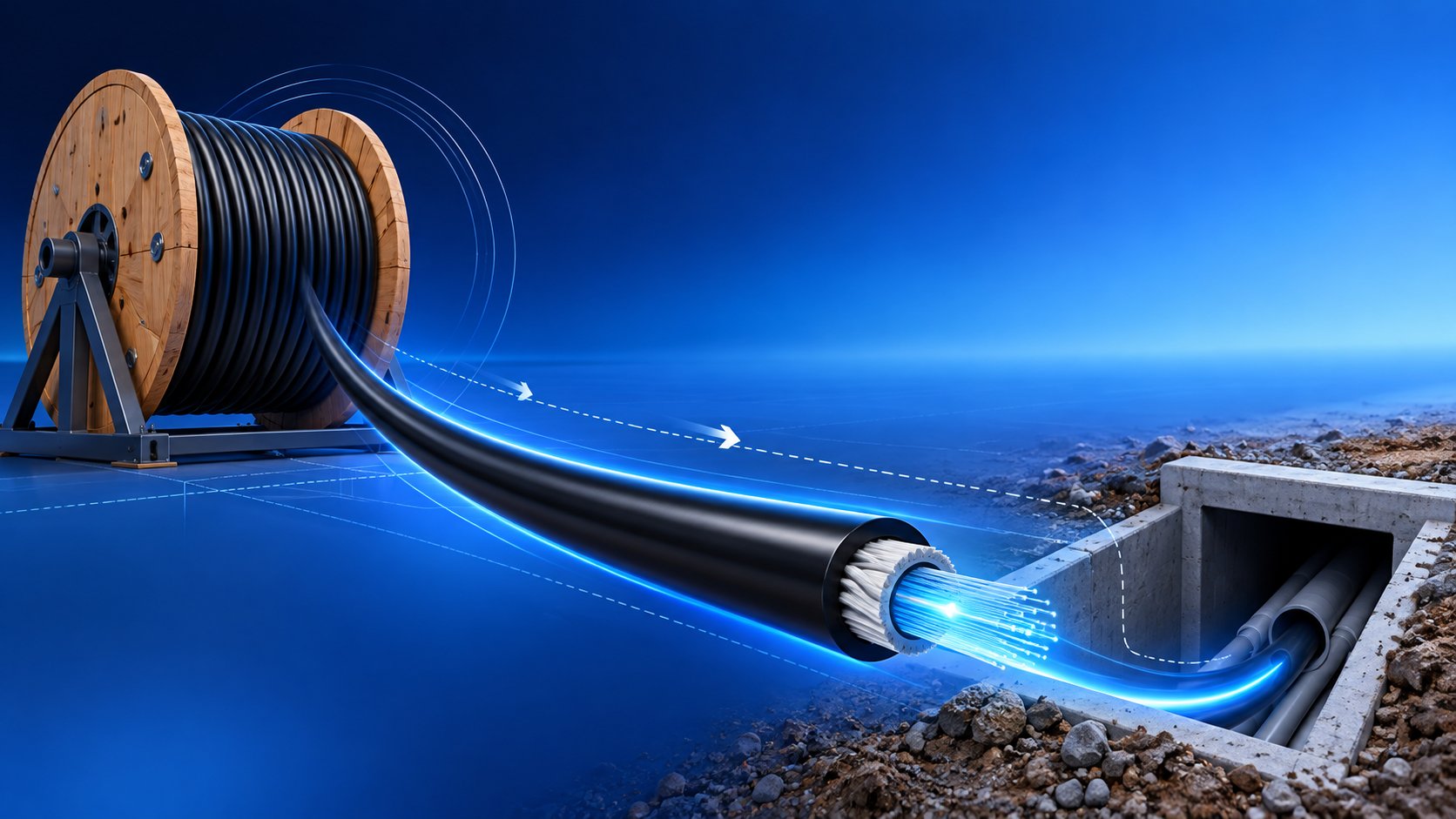
A contractor's guide to pulling fiber optic cable: short-term vs long-term tension limits, 20×OD bend radius rules, capstan-based pull planning, hardware, lubrication and post-pull verification, with typical values from Nexora's outdoor, armored, ADSS and figure-8 cable families.
On paper, a fiber optic cable pull looks simple: attach the cable to a winch, feed it into a duct, and watch it arrive at the far manhole. In practice, pulling is the step where the most expensive installation damage happens. A cable that is over-tensioned, twisted, or dragged around a corner tighter than its rated bend radius can be degraded before it is ever spliced, and the damage usually does not show up as a clean, immediate failure. It shows up later as attenuation drift, a marginal OTDR trace, or a fiber that breaks during splicing — after the trench has been backfilled, the ducts have been sealed, and the crew has moved to the next site.
That is why experienced contractors treat the pulling plan as an engineering task, not a labor task. Before the winch starts, they know three things: the maximum tensile load the cable is allowed to see, the minimum bend radius it must keep while under load, and how the friction along the planned route converts into actual pulling force. Every figure in this guide follows the same rule we apply on our own datasheets: the numbers printed on a specific cable's specification sheet govern, and the values in this article are typical industry figures for explanation. Where we quote Nexora cable families, the figures come from the published product pages for those cables, and each family's datasheet issued with the order restates the limits for the exact construction you bought.
The guide covers the physics that damages cable, the two limits every datasheet states, how to read them for loose-tube, armored, ADSS, and figure-8 constructions, the hardware and technique that keep a pull inside those limits, and the checks that confirm the cable survived. It is written for contractors, network builders, and project buyers who specify and purchase fiber optic cable for backbone, metro, access, and FTTH projects.
Why Cable Pulling Damage Is the Most Expensive Installation Mistake
Compare pulling damage with the other things that can go wrong on a fiber project. A bad splice is found during acceptance testing and re-made in minutes. A damaged connector is replaced on the spot. A damaged cable section, by contrast, is buried inside a duct or a trench. Repairing it means locating the fault, excavating or re-pulling a section, installing a new closure, and making two new splices — and every circuit riding on that cable has an outage while the work happens. On a direct burial backbone, the cable itself is one of the cheapest line items in the project; the civil work around a single buried repair is what makes the event expensive. This is the same economics that drives cable selection on unprotected routes, which we cover separately in our guide to armored fiber optic cable.
Pulling damage has a second unpleasant property: it is often invisible at handover. A loose-tube cable pulled at two or three times its rated short-term tension may still pass a continuity check. The glass may carry micro-cracks that grow under the residual stress, or the fiber may have been strained slightly beyond its elastic limit, raising attenuation a fraction of a decibel that grows with temperature cycles over the following months. By the time the link fails its loss budget, the pulling logs are long gone and no one can prove what force the cable actually saw. This is why a dynamometer on the winch and a written pull plan are not bureaucracy — they are the only record of what the cable experienced.
The good news is that pulling damage is almost entirely preventable. The limits are published, the physics is well understood, and the hardware that keeps a pull safe — pulling grips, swivels, lubricant, sheaves, and tension monitoring — is inexpensive compared with a single re-excavation. The rest of this guide turns those pieces into a repeatable procedure.
What Actually Happens Inside a Cable When You Pull Too Hard
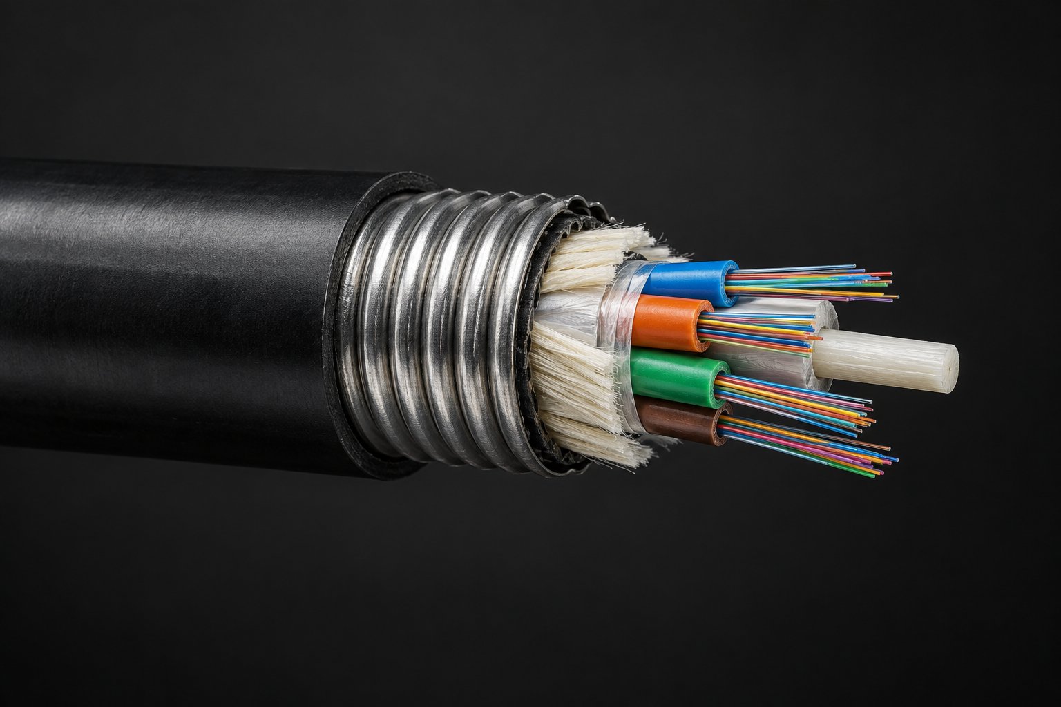
Understanding the failure mechanism makes the limits intuitive instead of arbitrary. A fiber optic cable concentrates all of its optical function in hair-thin glass fibers, each protected by a soft coating, a gel-filled loose tube or tight buffer, water-blocking yarns and tapes, and one or more strength members. The strength members — steel wire, FRP rod, or aramid yarn — exist precisely so that the plastic components and the glass never have to carry meaningful tensile load. When you pull the cable correctly, the strength members take the force and the fibers ride along neutrally.
When pulling tension exceeds the cable's rating, three things happen in escalating order. First, the cable itself begins to stretch permanently. A loose-tube construction stretched past its short-term rating elongates relative to its tubes, and the fibers inside, which are laid with slight excess length precisely to absorb this, start to consume that excess. Second, if the strain continues, the glass itself is put under tension. Glass under tensile stress develops and grows micro-cracks; this is static fatigue, and a fiber that survives the pull can fail weeks or months later at a fraction of the original load. Third, the mechanical structure deforms: tubes hockle, the core buckles inside the jacket, and the geometry that kept microbends low is lost. Attenuation rises, often at 1550 nm first because that wavelength is more sensitive to bend-related loss.
Bending damage follows a parallel logic. Every bend radius minimum exists to keep the light guided. Bend the fiber tighter than its rated radius and some of the guided light leaks out of the core — a macrobend loss that is measurable and mostly reversible if the bend is removed. Hold the fiber at that radius under tension, however, and the combination does two worse things: it presses the fiber against hard surfaces inside the cable, creating microbends, and it stresses the glass at the bend point, accelerating the same crack-growth mechanism as over-tensioning. This is why datasheets always state two bend figures — a larger radius while the cable is under pulling load, and a smaller radius once it is installed and at rest — and why the under-load figure is the one that matters on pull day.
Twist is the third damage mode, and it is the one crews most often ignore. If a winch line rotates under load and the cable is attached directly, every rotation puts twist into the cable. Twisted loose-tube cable wants to kink; kinked cable concentrates an enormous local bend in centimeters. The fix is mechanical and cheap: a swivel between the pulling grip and the winch line, which we cover in the hardware section.
One more mechanism is worth naming because it drives route planning: sidewall pressure. When the cable is under tension and passes over a bend — a duct corner, a sheave, the lip of a manhole — the tension presses the cable against the bend surface. That pressure per unit of contact is sidewall pressure, and it is the product of pulling tension and bend curvature. The same corner is harmless at low tension and crushing at high tension. This is why the two limits interact: as a pull gets longer and tension builds, every remaining corner becomes more dangerous, and the correct response is to reduce tension (shorter pulls, better lubrication, mid-route assists) rather than to simply hope the corners hold.
The Two Numbers That Govern Every Pull: Maximum Tension and Minimum Bend Radius
Open any properly written fiber optic cable datasheet and you will find two mechanical figures that matter more than every other number on pull day: the maximum tensile load and the minimum bend radius. Everything else in the pulling plan — pull length calculations, winch settings, sheave placement, lubrication — exists to keep the cable inside those two figures from the drum to the termination.
Maximum tensile load: short-term and long-term
Datasheets state tensile limits in two ratings, and confusing them is a classic planning error. The short-term rating (sometimes called maximum installation load) is the force the cable may see transiently during installation — the pulling force, plus the capstan effects of corners, plus any anchor loads while the cable is being hauled and set. The long-term rating (sometimes called maintained load) is the force the cable may carry continuously in service — for a vertical riser, the weight of the cable hanging on its own attachment; for aerial constructions, the residual tension after sag is set.
The practical rules that follow from these definitions are simple. During the pull, keep measured tension at or below the short-term rating, and plan for it to be comfortably below — a pull that runs at 90% of the limit from the first meter has no margin left when friction or a corner adds force partway through. After installation, make sure the cable is not left carrying load above the long-term rating: transfer hanging weight to approved clamps, leave slack loops at terminations, and on aerial routes set sag so that the cable's standing tension stays inside the long-term figure. On our outdoor loose-tube cable, for example, the published figures for a steel-wire strength member are 1,500 N short-term against 600 N long-term at 2-12 cores, rising to 2,700 N short-term and 1,000 N long-term at 216-288 cores; FRP builds carry roughly 20-25% lower tensile ratings at the same core count. Those are typical values for that family — the datasheet issued with your order states the limits for your exact configuration, and it governs.
Minimum bend radius: under load and at rest
Bend radius is specified as a multiple of the cable's outside diameter, which is why the same "20×" rule produces different millimeters for different cables. During the pull, when the cable is under tension, the minimum is the larger figure. Once the cable is installed, terminated, and at rest, the permitted radius drops — but never to zero, and the at-rest figure still governs every permanent bend from the duct exit to the splice tray.
Worked examples make this concrete. Our outdoor loose-tube construction specifies 20 × OD during installation and 10 × OD in service; for a 12 mm cable that is 240 mm while pulling and 120 mm once fixed. The armored family specifies 20 × OD under pull load and 15 × OD installed, so a 12 mm armored cable needs roughly 240 mm of radius while under load and 180 mm at rest — a reminder that adding armor changes the geometry, not just the strength. ADSS and figure-8 constructions in our range use the same 20 × OD installation / 10 × OD service pattern as typical values. Wherever a manhole corner, sheave, or duct sweep must be smaller than these figures, the route needs larger hardware or a different path — the cable cannot be persuaded to violate its radius by pulling harder.
Where these limits come from
Tensile and bend ratings are established by mechanical testing to recognized standards — tensile behavior to IEC 60794-1-21 for outdoor cable families, crush and impact to the method E3/E4 procedures in the same standard series. Manufacturers then apply design margins between the tested behavior and the published rating, which is why two cables of similar construction can carry different published limits. The practical takeaway for buyers is not to average or extrapolate datasheets: take the limits from the datasheet of the construction you actually ordered, and treat any figure in an article — including this one — as typical context until that datasheet confirms it.
How Pulling Limits Are Stated Across Common Cable Families
Because this guide quotes real constructions, it is worth laying the four families side by side. All figures below are the typical published values from the corresponding Nexora product pages; the datasheet issued with your order states the limits for your exact build and governs.
| Parameter | Outdoor loose-tube (G.652D) | Armored (steel tape / steel wire) | ADSS | Figure-8 self-supporting |
|---|---|---|---|---|
| Maximum tensile, short term | 1,500 N (2-12 cores) to 2,700 N (216-288 cores) | Up to 3,000 N steel tape; up to 6,000 N steel wire | Installation tension typically not more than 20% of rated tensile strength | Messenger carries the load; follow manufacturer pulling limits |
| Long-term / standing tension | 600 N to 1,000 N by core count | Confirm per datasheet | Set by sag and clamping design | Carried by messenger, not the core |
| Min. bend radius, under pull load | 20 × OD | 20 × OD | 20 × OD | 20 × OD (typical) |
| Min. bend radius, installed | 10 × OD | 15 × OD | 10 × OD | 10 × OD (typical) |
| Structure | Gel-filled loose tubes, steel wire or FRP center member, black PE jacket | Steel tape or steel wire armor under a water-blocking PE jacket | All-dielectric, aramid yarn strength, UV-resistant PE | Figure-8 profile: optical core plus integrated steel or FRP messenger |
| Typical deployment | Direct burial, duct, aerial (lashed or on support) | Direct burial, duct, rodent-prone and high-crush routes | Aerial on power poles and towers | Aerial spans, rural and urban distribution |
Three observations fall out of the table. First, the pull-load bend radius of 20 × OD is remarkably consistent across families, which makes it a good default planning figure — but the installed radius differs (10 × OD for unarmored and self-supporting types, 15 × OD for armored), so the geometry you leave the cable in at rest must be checked against the right column. Second, tensile capacity is spread over a wide range even within one family: our outdoor loose-tube cable’s short-term rating nearly doubles from small-core to high-core builds, because a larger cable simply carries more strength member. Never transfer a tension limit from a 12-core datasheet to a 144-core reel or the reverse. Third, aerial families express the limit differently: ADSS is planned against a percentage of its rated tensile strength rather than a fixed newton figure, because the right rating depends on the span and wind/ice loading of each route.
A note on drum lengths and pull planning
Cable is supplied on wooden drums — 2 km, 4 km, and 6 km are the standard lengths on our outdoor family — and the drum boundaries are themselves planning constraints. Every splice point is a closure, a bend-radius moment, and a slack loop, so the drum plan should follow the route's natural access points: manholes, handholes, pole lines, and building entries. A pulling plan that ignores drum boundaries and forces a mid-street splice will pay for it in labor and closure cost; a plan that places splices where crews and vehicles can actually work is cheaper for the life of the route. Confirm drum dimensions and gross weight with the quotation so lifting and transport are planned — a 2 km reel of small-core outdoor cable typically weighs on the order of a few hundred kilograms, and larger builds scale up from there.
Estimating Pulling Tension Before You Pull: The Capstan Effect
The pulling force a cable needs is not simply its weight over the route. Friction in a duct behaves like a capstan: every wrap of contact around a bend multiplies the tension by a fixed factor. The relation is the classic capstan equation: the tension leaving a bend equals the tension entering it multiplied by e to the power of μθ, where μ is the coefficient of friction between jacket and duct, and θ is the total angle of contact in radians. The consequence is exponential, not linear: two 90° bends at the end of a route multiply far more than two 90° bends at the start, because the incoming tension they multiply is already large.
What does that mean in practice? Coefficient-of-friction values depend on the jacket material, duct type, and lubrication; typical planning ranges run from roughly 0.5 for dry pulls in dirty conduit down to around 0.1 with a good lubricant, and your cable and lubricant suppliers can confirm workable figures. Even without exact numbers, the capstan model gives crews the two rules that save cables:
- Put the bends early, not late. Where the route allows a choice, arrange the pull direction so that the largest bends happen while tension is still low. Reversing the pull direction through the same manhole can cut peak tension dramatically.
- Count contact angle, not corners. A long sweep around a manhole wall may wrap 180° or more of effective angle even though it is "one corner." Total wrap angle is what the exponential sees.
A practical planning sequence used on real routes: break the route into straight segments and bends; assign a friction coefficient (dry or lubricated); compute tension step by step with the capstan factor at each bend, adding the straight-run friction (weight per kilometer times segment length times friction factor) along the way; and compare the predicted peak with the cable's short-term rating. If the prediction exceeds roughly 60-80% of the short-term limit, change the plan — not the cable's luck. The standard levers, in the order they should be used, are: better lubrication, reversing pull direction, relocating the winch to put bends early, splitting the pull with a mid-route assist or a figure-8 layout on the surface, and only as a last resort shortening the pull length by adding a splice point.
Two caveats keep the math honest. First, a calculation is only as good as its route survey: a duct that is partially blocked, contains water, or shares space with an old abandoned cable will not behave like the drawing. Second, predicted tension is not a substitute for measured tension — the winch or capstan must carry a dynamometer or load cell on pull day, and the crew should treat the calculated figure as the expectation against which the measured trace is compared. Our own product guidance for duct installation says exactly this: keep pulling tension below the short-term limit, monitor it with a dynamometer at the winch, and use a swivel to prevent twist.
Pulling Hardware: The Six Pieces That Protect the Cable
Good pulling practice is mostly about hardware. Six items do nearly all the protective work, and none of them is expensive relative to the cable they protect.
1. Pulling grip (pulling eye)
The grip is a woven mesh sleeve slipped over the cable end that transfers pulling force into the cable's strength members and jacket as a whole. Its critical rule: never attach a winch line to the fibers, the central strength member alone, or the jacket stripped back to expose internals. The grip must be sized to the cable's actual outside diameter — a grip that is too large slips and tears the jacket, one that is too small concentrates load at the mouth. For pulls where the cable end must survive to be spliced (most pulls), protect the cable end with an end cap during the pull so no water or grit enters the core.
2. Swivel
The swivel goes between the pulling grip and the winch line, and its whole job is to absorb the winch line's rotation instead of letting it twist the cable. As explained above, twist in a loose-tube cable converts directly into kink risk. A pulling rig without a swivel is incomplete, full stop.
3. Dynamometer / load cell
Tension that is not measured is only a hope. Modern winches and capstan pullers accept inline load cells that display and log the live tension; the operator watches the trace and stops the pull before it approaches the short-term rating. The log also becomes your acceptance record — the documented proof that the installation respected the datasheet, which matters both for warranty conversations and for diagnosing any later fault.
4. Winch or capstan puller with speed control
Pulling speed should be steady and moderate. High speed makes the pull harder to control at corners and multiplies the damage when something jams; stop-start jerking applies shock loads well above the steady-state reading. A steady walking-pace pull with smooth acceleration keeps measured tension close to the calculated value and gives the operator time to react. Where a mid-route assist is used (a second capstan at an intermediate manhole), the assist must be synchronized so the cable is never momentarily stalled under full winch tension at a capstan entrance.
5. Sheaves, rollers, and corner guides
Every point where the cable changes direction under load needs a sheave or quadrant block with a groove radius at least as large as the cable's under-load bend radius — the 20 × OD figure from the datasheet. At manhole entrances, a bell-mouth or radius guide protects the cable from the concrete lip; in trench work, rollers spaced along the route keep the cable off sharp stones and edges. A sheave that is undersized is worse than no sheave, because it enforces a violating bend under full tension.
6. Cable lubricant
Lubricant lowers the coefficient of friction, and on bend-heavy routes it lowers peak tension dramatically through the capstan effect — the benefit compounds at every corner. Modern lubricants are water-based, compatible with polyethylene and medium-density PE jackets, dry to a slippery film rather than staying wet, and safe for the cable's other materials. Apply it at the duct entrance as the cable feeds in, and on long or multi-bend runs re-apply at intermediate points. One caution: more lubricant is not automatically better — ponds of it in a manhole create housekeeping and disposal issues, and some legacy lubricants (wax- or grease-based) should never be mixed with modern polymeric ones, because the combination can gum up ducts.
Step by Step: Pulling Loose-Tube Cable into Duct
Most outdoor pulls happen in duct, and most pulling damage happens in duct, so the procedure deserves a full walk-through. The steps below assume a prepared route: ducts proven clear, drum positioned, hardware staged, and a calculated tension profile in hand.
Before the pull: prove the route
A duct that has never been proven is the single most common cause of a jammed pull. Swab or brush the duct to remove debris and standing slurry, use a mandrel of appropriate size to confirm the inner bore is clear along the whole run, and verify duct continuity. Where existing cables occupy the duct, confirm the fill leaves working clearance — congestion raises friction unpredictably and makes any mid-pull recovery far harder. Prepare the feeding manhole with a drum stand or roller payoff that lets the drum turn freely, and set up corner guides and the bell mouth at the receiving pit.
Set up the pulling end
Position the winch or capstan in line with the duct exit, attach the load cell, and rig the sequence exactly as it will run: winch line → swivel → pulling grip → cable end capped. Dress the cable from the drum through the payoff roller and into the duct entrance through a radius guide, so the cable's first meter inside the duct is already at a safe angle. Conduct a radio check between the winch operator, the feed point, and any intermediate manhole observers — a pull is a coordinated three-station operation, not a one-person job.
Run the pull
Start smooth and accelerate to a steady moderate speed. The winch operator watches the load cell continuously; the feed crew keeps slack out of the drum payoff and applies lubricant steadily at the entrance; intermediate observers watch each manhole to confirm the cable rides correctly over sheaves and is not snagging. If tension rises toward the planned ceiling — for our outdoor loose-tube family, that ceiling is the short-term rating of the specific core count, 1,500 N to 2,700 N as typical values — stop and diagnose rather than pushing through: a partial jam that is backed out and cleared costs an hour, while a jam forced at full tension costs the reel.
Do not stop for long pauses if it can be avoided: some lubricants drain or dry during a halt, and a restart in a dry bend can spike tension above the whole-pull maximum. If a stop is unavoidable, add lubricant at the last access point before restarting and pull the restart more slowly than the main run.
Land the cable
As the cable end arrives, slow down and finish by hand where possible, leaving the agreed slack at the termination or splice point — enough to reach the splice location with a service loop, plus the extra length for re-termination later. Cap the end immediately. In the manhole, secure the cable so it cannot shift back into the duct, and set it on supports rather than leaving it on the wet floor. Only then remove the grip — cutting it off, never unwinding it in a way that kinks the end.
Pulling in Open Trench and Direct-Buried Sections
Trench pulls look easier than duct pulls and have their own failure modes. The route is open, so friction is low and visibility is good — but the cable lies exposed on rocky ground, and the crew's habits decide whether it is protected.
Rollers spaced along the trench keep the cable off stones and sharp edges as it is hauled; where the cable leaves the trench to cross a road bore or enter a vault, the same sheave rules as duct work apply. Hand-laying sections are where bend discipline slips: crews casually coil cable around corners tighter than the installed radius allows. A useful site rule is to treat 20 × OD as the minimum for any temporary bend even when the cable is slack — it costs nothing and removes an entire class of damage. Bed preparation matters as soon as the cable is laid: the trench should offer a stable, stone-free bed with fine-material protection around the cable, per the installation notes on our armored and outdoor cable pages, so the armor is not point-loaded by sharp rock either during the pull or after backfill. Our guide to direct-buried installation covers trench depth, bedding, ducting, and backfill in detail.
Tension in trench sections is usually low enough to pull by hand or with light equipment, but the same load discipline applies wherever a winch is used — measured force, a swivel, and a grip sized to the cable. Where a trench run connects to a duct section, plan the transition as one tension calculation, because the duct segment's capstan effect dominates the total even if the trench part is frictionless.
Aerial Pulling: Tension Rules for ADSS and Figure-8 Cable
Aerial installations change the mechanics: instead of duct friction, the dominant forces are the cable's own weight, span tension, and the stringing hardware. Two constructions behave differently, and each has a firm rule.
ADSS: respect the percentage-of-RTS rule
All-dielectric self-supporting cable carries itself across the span on aramid yarn strength members, and its installation limit is expressed as a share of the cable's rated tensile strength — a typical planning rule for our ADSS family is that installation tension should not exceed about 20% of the rated tensile strength, with the project datasheet stating the figure for the actual construction. The RTS itself is sized to the route: span length, pole spacing, and wind and ice loading determine how much aramid the cable carries, so the same core count can exist in materially different strengths. Stringing practice follows directly: use tension stringing rather than dragging, keep the cable off the ground and out of contact with structures, run it over stringing blocks (sheaves) sized to the under-load bend radius, and pull with a winch and load cell as in duct work. The closure-side rules are equally mechanical: helical or suspension clamps matched to the cable diameter, no sharp bends at pole hardware, and sag set so that standing tension stays within the long-term design. Two properties make ADSS attractive on power corridors — no metal, so no grounding at each support, and no separate messenger — but they also mean the cable has no redundant load path: whatever tension the route imposes is carried entirely by the aramid inside the jacket, which is why the 20%-of-RTS ceiling is treated as a hard limit rather than a suggestion.
Figure-8: the messenger takes the load — if you rig it that way
Figure-8 self-supporting cable bonds a steel strand or FRP messenger to the optical core in one profile, so the single-pass pull is the entire installation. The messenger is designed to carry the span load and the stringing tension; the core rides alongside and should see almost none of it. Rig the pull so the grip and winch line engage the messenger web and the cable as a whole — not the core portion alone — follow the manufacturer's recommended pulling speed and tension for the construction, and keep the cable on stringing blocks through corners. After sag is set and the cable is clamped, leave a small service loop at each pole to absorb thermal movement, and leave adequate slack before the cable enters a distribution box or ODF at the span ends. The figure-8 construction is covered in depth, including messenger selection between steel strand and FRP, in our aerial deployment guide.
One cross-cutting aerial rule: weather governs the schedule. Wind loading during stringing raises both the actual tension and the difficulty of controlling blocks and cable ends; ice or wet jacket conditions change friction at the blocks. Pulling an aerial span in weather well outside the design assumptions risks both the crew and the cable, and a delay is cheaper than a re-string.
Bend Radius Management at Corners, Manholes, and Terminations
Because the under-load bend radius is the figure most often violated in the field, it deserves its own checklist. The violations cluster in five predictable places:
- Duct and manhole corners. Every change of direction the cable makes under tension must happen over a guide or sheave whose groove radius meets the 20 × OD under-load figure — never over a concrete lip, an unprotected duct edge, or a crew member's shoulder.
- The drum payoff. Cable coming off a drum under load wraps the drum flange if the payoff is misaligned; keep the drum square to the duct entry and let the payoff roller define the last bend.
- Vertical risers. At the top of a riser, the cable's hanging weight becomes continuous tension; transfer it to approved clamps at the design intervals and keep the riser's corner bends inside the installed radius where the cable is at rest, and inside the under-load radius wherever it may still be under load during settling.
- Splice closures and slack storage. Slack loops store cable, but they must be coiled larger than the installed bend radius and secured so the loop cannot migrate into a smaller radius over time. This matters doubly where a future crew will open the loop and re-work the splice — an unkempt slack loop becomes a kink the moment someone pulls on it.
- Terminations into cabinets and ODFs. The last meter before a patch panel or ODF is dense with tight geometry; route the cable through the cabinet's designed bends and reserve the small radii for the patch cords and pigtails inside the tray, which are built for them, rather than for the outside plant cable, which is not. Our ODF and rack termination guide covers that geometry in detail.
A practical training rule for crews: if the cable is being bent by hand around a corner with no guide, stop and build the guide. The few minutes of rigging are always cheaper than a section of degraded fiber.
Seven Pulling Mistakes That Damage an Otherwise Good Cable
Across audits of failed installations, the same mistakes recur. They are listed here in the order they tend to occur on a working day.
- 1. Pulling without measuring tension. The calculated number replaces the measured one, and the crew discovers at splice time that the pull ran far past the limit. A load cell on the winch is the cheapest insurance on the project.
- 2. No swivel. Winch line rotation transfers twist into the cable; twisted loose-tube cable kinks. The swivel costs a fraction of one closure.
- 3. Ignoring the capstan effect. A route with two "easy" bends at the far end exceeds the limit that the same route would have with the bends at the near end. Plan pull direction around bend placement.
- 4. Undersized or improvised bends. Cable pulled over a manhole lip, a truck bumper, or a crew member's boot concentrates sidewall pressure exactly where no one is watching.
- 5. Dry pulls in dirty duct. Skipping the swab and the lubricant to save an hour multiplies friction along every meter and at every bend; the jam it produces usually costs the pull and sometimes the duct.
- 6. Dragging cable across ground, racks, or around corners during "slack" phases. The short-term rating applies to the total force, including the force from dragging; and abrasion damage to the jacket may not show until water finds the core months later.
- 7. Leaving the cable loaded after installation. The long-term rating is much lower than the short-term rating; a cable left hanging on its own grip at a manhole wall, or with its slack pinched at a duct exit, is carrying continuous load it was never rated for. Transfer to clamps, coil the slack, cap the end.
Worth stating plainly: manufacturing defects and installation damage are different things, and warranties treat them differently. Our cables carry a 12-month warranty from the shipment date covering manufacturing defects; damage caused by installing beyond the rated bend radius or tensile load is outside that scope — one more reason the tension log and the pull plan are part of professional handover documentation.
After the Pull: Verifying the Cable Survived
Verification belongs to pull day, not handover week, because it is the only time a fault can still be fixed before the route is closed up. The sequence that works:
- Visual check at both ends. Jacket abrasion, gouges, kinks, or a visibly flattened section anywhere accessible means that section is flagged now, while the reel documentation and pull log are still in hand.
- End-to-end fiber check. Continuity and attenuation on every fiber, using a light source and power meter for a fast pass/fail, and an OTDR for the full picture. The OTDR is the tool that finds what the eye cannot: a localized loss spike at a manhole where sidewall pressure peaked, or a rising baseline that signals strained fiber. Our guide to OTDR acceptance testing covers the trace-reading procedure and baseline documentation.
- Compare against the loss budget. Measured attenuation should sit inside the link budget computed for the route — fiber attenuation at the specified wavelength plus splices plus connectors plus margin. A link that passes its budget today still gets its OTDR baseline recorded, because the baseline is what makes a future drift diagnosable.
- Document everything. Route as-built (drum numbers, splice locations, slack loop positions), the tension log from the winch, and the optical results belong in the project file together. Six months later, that combination is the difference between a five-minute diagnosis and a week of excavating guesses.
Where the verification finds a problem, the economics argue for fixing it before closure: re-pulling a duct section or re-laying a trench segment costs a fraction of the same repair after backfill and commissioning.
A Buyer's Checklist: What to Confirm with Your Cable Supplier Before Pull Day
Most pulling problems are actually procurement problems — limits that were never communicated from the datasheet to the crew. Before the pull, confirm these items with your supplier and put them in the work plan:
- Maximum tensile load, short-term and long-term, for your exact construction. Not the family brochure figure — the datasheet for your core count, strength member, and armor type. On our outdoor loose-tube family, for instance, the typical short-term figure moves from 1,500 N at 2-12 cores to 2,700 N at 216-288 cores, and FRP builds run roughly 20-25% lower than steel-wire builds at the same core count.
- Minimum bend radius under load and installed, in millimeters. Ask for the millimeters, not just the multiplier — crews work in millimeters.
- Recommended pulling method for the deployment. Duct, direct burial, and aerial each have supplier guidance; on aerial constructions, ask for the installation tension limit (for ADSS, the percentage-of-RTS figure) and the recommended stringing-block sizes.
- Drum lengths and reel weights, so the pull plan matches the physical drum boundaries, and lifting gear matches the reel.
- Jacket and lubricant compatibility. Modern water-based lubricants are compatible with PE jackets; confirm if your route reuses old ducts with legacy lubricant residue.
- Test documentation shipped with the reels. Every reel should carry its attenuation test report on request, and the reel label should identify fiber count, fiber type, and length — the anchors for acceptance testing.
- Warranty scope in writing. All Nexora fiber optic cables carry a 12-month warranty from the shipment date covering manufacturing defects, with a defined claim process (reel number, test report, and fault description) and stated response times. Knowing the scope before the pull also clarifies why the installation records matter.
If you are at the RFQ stage, our guide to writing a fiber optic cable RFQ lists the route and construction details worth including so the supplier can quote the right build — and the right pulling limits — the first time.
Frequently Asked Questions
What is the maximum pulling tension for fiber optic cable?
There is no single industry number: the limit is stated per construction on the datasheet. Typical published short-term ratings for outdoor loose-tube cable in our range run from 1,500 N for small-core builds to 2,700 N for 216-288-core builds; armored constructions reach up to 3,000 N with steel tape and up to 6,000 N with steel wire armor; and ADSS is planned against a limit of roughly 20% of its rated tensile strength. Treat every figure as typical until the datasheet for your ordered construction confirms it.
Can I exceed the short-term rating briefly if the pull is almost done?
No. The short-term rating is a transient installation ceiling, not a target, and glass fiber damage from over-tension is cumulative and partly delayed — a fiber that survives the pull can fail later under residual stress. If tension approaches the limit, stop and fix the cause: more lubricant, a mid-route assist, or a reversed pull direction.
Why is the bend radius larger while pulling than after installation?
Under tension, the cable presses outward against any bend (sidewall pressure), which both stresses the fiber mechanically and creates microbends that raise attenuation. The under-load radius (typically 20 × OD across our outdoor, armored, and self-supporting families) keeps that pressure safe; once installed and at rest, the permitted radius drops to the installed figure (10 × OD for unarmored and self-supporting types, 15 × OD for armored).
How long can a single duct pull be?
Long enough only if the calculated peak tension stays comfortably below the cable's short-term rating. The capstan effect means bend-heavy routes exhaust the limit quickly; the standard remedies are better lubrication, reversing the pull direction so bends come early, splitting the pull at an intermediate manhole with a second capstan, or adding a splice point. The right answer is a route calculation, not a rule of thumb.
Do I need a pulling grip even for a short hand pull?
Yes, wherever any winch or pulling force is applied. A grip distributes load into the strength members and jacket; grabbing the cable end with a knot or a clamp concentrates force on exactly the components that cannot take it. For genuinely short, gentle hauls by hand, a properly fitted grip is still the cheapest way to avoid a damaged end.
Does pulling damage show up on the warranty?
Warranties cover manufacturing defects, not installation damage. Nexora cables, for example, carry a 12-month warranty from the shipment date covering manufacturing defects, while damage from installing beyond the rated bend radius or tensile load falls outside that scope. This division is why the pull log — measured tension, route, and hardware — is part of a professional installation record.
What pulling speed should we use?
Steady and moderate, at a speed the whole crew can coordinate and the winch operator can arrest quickly. Jerky, stop-start pulling applies shock loads above the steady reading, and very high speeds make corner events harder to catch. Follow the winch manufacturer's speed range and the cable supplier's recommendations; consistency matters more than speed.
Conclusion: Treat the Pull as the Test It Is
A cable pull is the first mechanical test your fiber will ever undergo — and the only one it may not survive. The discipline that keeps it safe is neither exotic nor expensive: know the short-term tension limit and the under-load bend radius for the exact construction on the drum, calculate the route's friction before rigging, measure tension live with a swivel and a grip in the rig, keep every bend guided to radius, lubricate duct pulls, and verify optically before the route is closed. Do that, and the cable's published limits become routine numbers on a checklist instead of a repair invoice.
Nexora manufactures outdoor loose-tube, armored, ADSS, and figure-8 self-supporting fiber optic cable in Shenzhen, with fiber counts from a few cores up to 288, typical drum lengths of 2-6 km, and datasheets that state the tensile and bend limits for each ordered construction. All products carry a 12-month warranty from the shipment date, and performance figures in this article are typical industry values for guidance — the specification sheet issued with your order governs. If you are planning a route and want the pulling limits, drum plan, and construction options confirmed for your project, tell us your core count, deployment method, and route length, and our team will confirm the matching build.