
Nexora
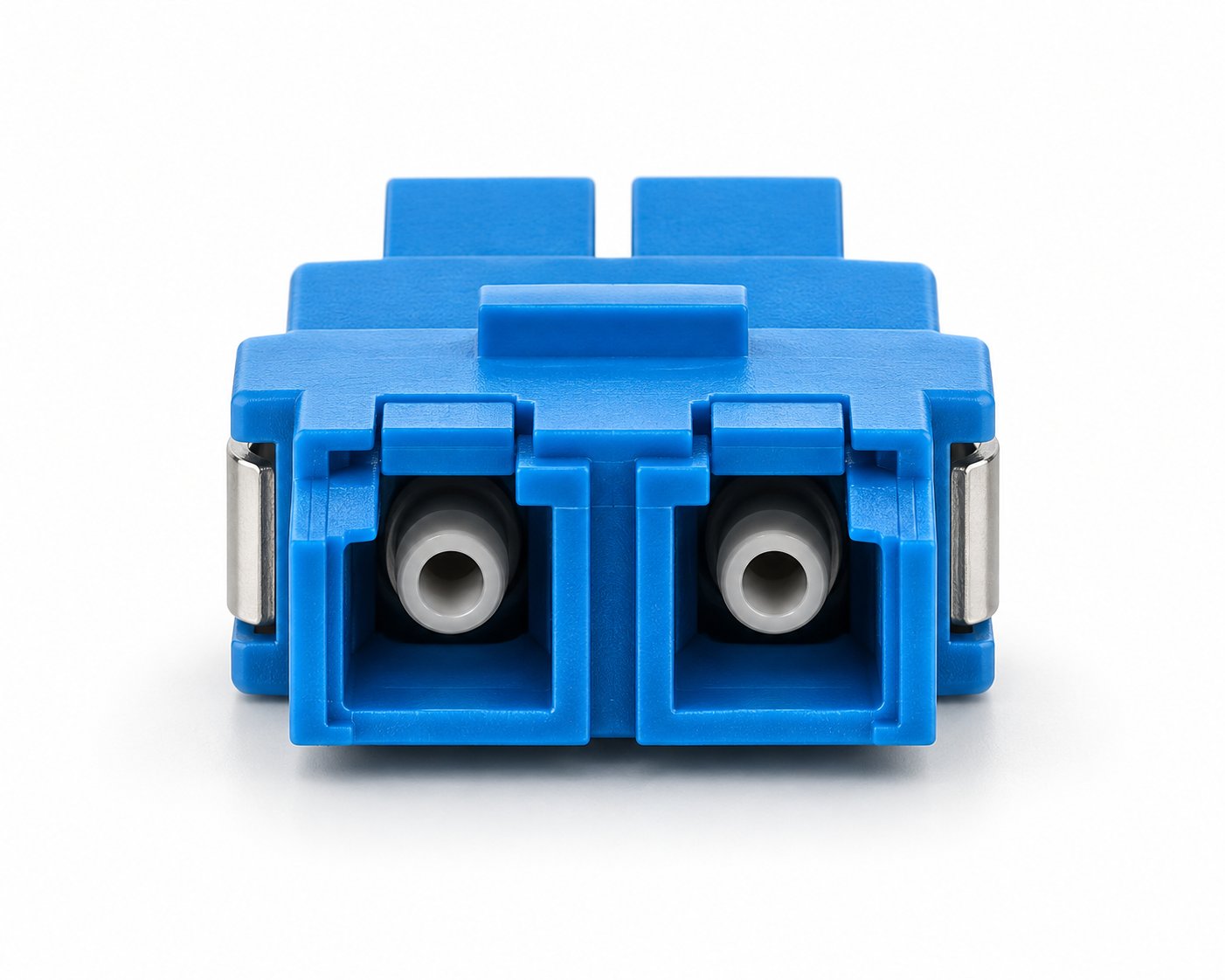
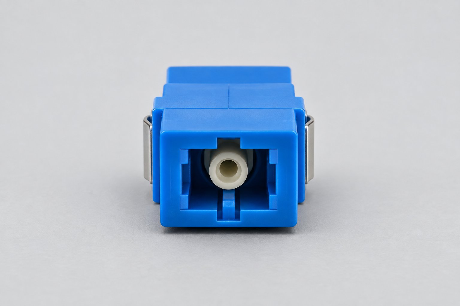
LC/UPC Duplex Fiber Optic Adapter
LC/UPC duplex fiber optic adapter for high-density data center and LAN connections, with precise alignment and low insertion loss.
Fiber Type
Single mode / multimode
Connector
LC/UPC
Connector Type
LC/UPC, duplex
Product Notes
- Compact duplex design
- Low insertion loss
- Custom flange options
Specifications
Fiber type, connector, test data, packaging proof and sample-kit notes are kept in the same quote sheet.
| Connector Type | LC/UPC, duplex |
|---|---|
| Fiber Type | Single mode / multimode |
| Insertion Loss | <= 0.2 dB (typical, at 1310/1550 nm, mated with LC/UPC connectors) |
| Return Loss | >= 50 dB (UPC, at 1310/1550 nm) |
| Type | Duplex |
| Flange | Flanged / unflanged |
| Application | Data centers, patch panels, LAN |
| Alignment Sleeve | Precision ceramic (zirconia) |
| Body Dimensions | Approx. 12.7 x 9.6 x 29.5 mm (typical) |
| Operating Temperature | -40 C to +85 C (typical) |
| Warranty | 12 months from shipment date |
Application Notes
One problem that decides whether a high-density LC/UPC panel stays within budget
A 48-port LC/UPC patch panel holds 48 duplex adapters, which means 96 mated LC connections in a single 1U space. If each LC/UPC adapter adds 0.2 dB of insertion loss, the panel alone consumes 0.2 dB of the link budget; if the alignment sleeve lets the ferrules sit slightly off-axis, that figure can drift upward after repeated patching, and a link designed with a 3 dB margin can start failing acceptance tests during commissioning.
The measurable risk is not the adapter's first-day reading but its reading after the panel has been re-patched. Field crews typically re-patch a high-density panel dozens of times during build-out and moves, adds and changes. A sleeve that wears unevenly lets the two LC/UPC ferrules drift off the common axis, so insertion loss creeps up and return loss drops. For a single mode link running at 1310 nm or 1550 nm, a return loss that falls below the 50 dB UPC threshold is the failure mode that shows up first on an OTDR trace.
How this LC/UPC duplex adapter holds the connection
This LC/UPC duplex fiber optic adapter uses a precision ceramic (zirconia) alignment sleeve that keeps both LC/UPC ferrules centered on the same axis and in physical contact. The LC/UPC adapter is specified to hold an insertion loss of <=0.2 dB and a return loss of >=50 dB for UPC polish when mated with LC/UPC connectors. Those figures are the values the adapter is designed to hold at the mated pair, measured at 1310 nm and 1550 nm; the final link budget still depends on the fiber type and the connectors you pair with it.
The duplex body carries both fibers of a pair in one housing, so the transmit and receive paths stay together. In a 1U panel this halves the number of cutouts compared with running two simplex adapters side by side, which keeps labeling and cable management simpler during moves, adds and changes.
Flange options and how to choose
The adapter is available in flanged and unflanged versions. A flanged adapter has a mounting lip that snaps or screws into a cutout in the patch panel, which is the common choice for a fixed panel where the adapter must stay in place. An unflanged adapter is pressed into a sleeve or holder and is easier to remove, which suits modular or field-replaceable layouts. If you are not sure which fits your panel, the flange type is one of the details to confirm with your panel supplier before ordering.
Dimensions and panel cutout
For a flanged LC/UPC adapter, the panel cutout is the dimension that decides whether the part fits, so it is worth confirming before ordering rather than after the panel is punched. The table below lists the body and cutout dimensions to check against your panel drawing.
| Dimension | Value |
|---|---|
| Adapter body (H x W x D) | Approx. 12.7 x 9.6 x 29.5 mm (typical, duplex LC body) |
| Flange mounting cutout | Rectangular cutout with two M2 mounting holes; confirm against your panel drawing |
| Panel thickness | Suited to standard sheet-metal panel thickness; confirm for thick or double-wall panels |
Dimensions are typical values for the duplex LC body; send your panel drawing with the inquiry and the cutout can be confirmed against it before production.
Single mode and multimode use
The adapter accepts both single mode and multimode LC/UPC connectors. The insertion loss and return loss figures above are the values the adapter is designed to hold when mated with LC/UPC connectors; the actual link budget still depends on the fiber type and the connectors you pair with it. For a single mode link, the >=50 dB return loss matters most. For a multimode link, the same low insertion loss keeps the short-haul budget healthy.
Specifications
| Parameter | Value |
|---|---|
| Connector Type | LC/UPC, duplex |
| Fiber Type | Single mode / multimode |
| Insertion Loss | <= 0.2 dB (typical, at 1310/1550 nm, mated with LC/UPC connectors) |
| Return Loss | >= 50 dB (UPC, at 1310/1550 nm) |
| Alignment Sleeve | Precision ceramic (zirconia) |
| Type | Duplex |
| Flange | Flanged / unflanged |
| Body Dimensions | Approx. 12.7 x 9.6 x 29.5 mm (typical) |
| Operating Temperature | -40 C to +85 C (typical) |
| Application | Data centers, patch panels, LAN |
| Warranty | 12 months from shipment date |
Values marked typical are the figures the adapter is designed to hold under the stated mating conditions; confirm against the datasheet for your order.
How each LC/UPC adapter is inspected before packing
Every LC/UPC adapter passes through the same inspection sequence before it is packed, and each stage has a defined sampling rule and accept/reject limit rather than a visual pass only:
- Incoming material: ceramic sleeves and housings are checked against the drawing for bore diameter and concentricity; a sampling plan is applied per incoming lot.
- In-process: sleeve seating and body assembly are checked for full insertion and correct orientation before the housing is closed.
- Functional: insertion loss and return loss are measured on the mated pair at 1310/1550 nm with an optical loss test set; units outside the <=0.2 dB and >=50 dB limits are rejected and not packed.
- Visual: the end face and housing are inspected for scratches, contamination and moulding defects.
- Final and packaging: label, quantity and carton are confirmed against the packing list before shipment.
Rejected units are separated from the lot and are not mixed back into the shipment. The inspection record for the batch travels with the order, so a buyer receiving a mixed shipment can trace which batch each carton came from.
Installation and maintenance notes
Because the failure mode described above starts at the end face, the handling routine matters as much as the adapter itself. Before mating, clean both LC/UPC connector end faces and inspect them; a contaminated end face is the most common cause of a return loss reading that falls below the 50 dB threshold. Seat the connector until it latches, and avoid pulling on the cable to release it. For a flanged adapter, tighten the mounting screws evenly so the body is not distorted in the panel cutout. In a high-density panel, re-check insertion loss on a sample of ports after a large moves, adds and changes cycle rather than assuming the panel is unchanged.
Production background
Nexora has manufactured fiber optic connectivity products since 2014, operates 12 production lines in a 16,000 sqm facility with 180+ employees, and has an annual capacity of 2.8M units. The company runs 30+ QC stations across incoming material, component, in-process, functional, visual, final and packaging inspection, and has delivered 500+ OEM/ODM projects for customers in 50+ countries. These are company-level manufacturing facts; they describe the facility that produces this adapter, not a product-specific certification.
Customization for OEM and ODM projects
For an OEM or ODM project, the LC/UPC adapter can be configured around your requirements. The table below sets out what can be changed and what each change involves, so you can judge feasibility before sending an inquiry.
| Customizable item | Scope and conditions |
|---|---|
| Flange style | Flanged or unflanged; confirmed against your panel cutout drawing |
| Body color | Standard colors: blue (single mode UPC), green (APC), beige (multimode); custom color confirmed per order |
| Packaging | Bag, inner box and carton labeling can follow your requirement |
| Logo or marking | Confirmed per project; marking method and artwork requirement agreed before sampling |
| Sampling | A sample can be developed from the existing product range for ODM projects; sample cost and schedule are confirmed with the quotation |
If you supply a drawing, technical parameters or a reference sample, Nexora can produce to that specification. The exact customization scope and lead time are confirmed against your order, so include the flange type, color and quantity in your inquiry.
Ordering, packing and delivery
| Item | Detail |
|---|---|
| MOQ | 1,000 pcs for standard configurations; custom flange or color confirmed per order |
| Sample | Available for evaluation; sample cost and freight confirmed with the quotation |
| Standard packing | Anti-static bag per adapter, then inner box, then export carton |
| Carton quantity | Confirmed per order based on configuration and destination |
| Lead time | Typically 7-15 working days for standard orders, counted from deposit receipt and artwork approval; custom orders confirmed per order |
| Payment | T/T; other terms confirmed with the quotation |
| Warranty | 12 months from shipment date |
Lead time and carton quantity are typical figures for planning; confirm them against your order before scheduling installation.
Buying FAQ
What is the difference between flanged and unflanged LC/UPC adapters?
A flanged adapter has a mounting lip that fixes it into a patch panel cutout and stays in place. An unflanged adapter is pressed into a holder and is easier to remove for modular layouts. Choose based on how your panel is built; confirm the cutout type with your panel supplier if you are unsure.
Does this adapter work for both single mode and multimode fiber?
Yes. The adapter accepts LC/UPC connectors for both single mode and multimode fiber. The insertion loss of <=0.2 dB and return loss of >=50 dB are the values the adapter is designed to hold when mated with LC/UPC connectors at 1310/1550 nm; the final link budget also depends on the fiber and connectors you pair with it.
What is the MOQ and typical lead time?
MOQ is 1,000 pcs for standard configurations; custom flange or color is confirmed per order. Standard orders typically ship in 7-15 working days counted from deposit receipt and artwork approval, and custom orders are confirmed against your order.
How is the adapter packed for export?
Each adapter is packed in an anti-static bag, then an inner box, then an export carton. Carton quantity is confirmed per order based on configuration and destination.
What warranty applies?
The adapter carries a 12-month warranty from shipment date. Report any defect with the batch and quantity so it can be traced against the inspection record.
Can I order a custom flange or color?
Yes. Flange style, body color, packaging and marking can be configured for OEM and ODM projects. Include the flange type, color and quantity in your inquiry so the configuration can be confirmed against your order.
Request product details
Tell us the flange type (flanged or unflanged), body color, quantity and whether you need a standard or custom configuration. We will confirm the specification and lead time against your order.
Tags
Related Fiber Products
Get A Quote
Send fiber type, connector, quantity, application and packaging requirement. The response can include test data and sample-kit notes.
OEM & Customization
Connector types, fiber counts, cable lengths, jacket materials and packaging can be configured to your project specification.
Technical Support
Our engineering team helps you confirm product selection, installation details and documentation before you place the order.
Quality & Testing
Every order is inspected before shipment, and test data or inspection reports can be provided with the goods on request.