

A practical B2B guide to fiber optic connector cleaning and end-face inspection: IEC 61300-3-35 workflows, dry and solvent cleaning rules, maintenance schedules, and what to specify on the supply side.
Most fiber optic link failures traced back to hardware turn out not to be failures of the cable at all. They are failures at the mating interface: two ferrule end faces that should meet in clean, controlled physical contact, and do not. Contamination on a connector end face is routinely identified by field engineers as the leading cause of optical link degradation, ahead of macrobends, damaged cable and transceiver faults. The reason is simple arithmetic — a single speck of dust on a single-mode ferrule can add several tenths of a decibel of loss, and a single-mode link is often designed with less than 3 dB of total margin — and simple geometry, because anything trapped between two physical-contact end faces holds them apart at exactly the point where light crosses the joint.
Yet connector cleaning and end-face inspection remain the most skipped steps in network practice. Installation crews are measured on links passing a continuity check, and a dirty connector often passes one. The cost of that skipped step does not appear at commissioning. It appears weeks or months later as an intermittent alarm, a degraded error-rate margin, or an unexplained outage that consumes a maintenance window and a truck roll. This guide is written for network engineers, contractors, integrators and procurement teams who specify, install and maintain fiber optic infrastructure, and who want a repeatable, defensible procedure for keeping mated connections inside their loss budget over the life of the network.
Why Connector End Faces Are Where Fiber Networks Actually Fail
A fiber optic connector is a precision mechanical part. The ferrule — the white ceramic or composite cylinder at the tip of the connector — holds the fiber so that its core lands within a fraction of a micron of the mating fiber's core. The alignment sleeve inside the adapter holds the two ferrules concentric while a spring behind the ferrule presses the polished end faces into physical contact. When everything is clean and correctly seated, a mated single-mode connection adds around 0.1 to 0.3 dB of loss and reflects very little light back toward the transmitter.
When contamination sits between those end faces, three things happen at once. First, the contaminant props the ferrules apart, creating a microscopic air gap at the core that adds insertion loss. Second, that air gap creates a glass-to-air-to-glass interface that reflects light — the very effect that physical-contact polishing is designed to eliminate — so return loss degrades and the reflected component travels back toward the laser. Third, and less obviously, the contaminant does not stay put: it is compressed and dragged across the soft polished glass by the spring pressure, it can transfer to the alignment sleeve, and from the sleeve it contaminates the next connector plugged into the same port.
This is why a dirty connection is rarely a one-port problem. In a populated patch panel, one contaminated connector mated into a dirty adapter can pass contamination to several good jumpers in succession. Field technicians who routinely open panels will recognize the pattern: one "bad port" that follows a jumper around, because the jumper was never the problem — the adapter sleeve was.
The economics are what make this worth managing deliberately rather than reactively. Every troubleshooting visit to a live site carries a cost that is easy to estimate: a technician, transport, and a maintenance window, often coordinated across time zones on a customer's network. A preventive cleaning and inspection pass across a panel takes minutes per port. Compare that with isolating one high-loss port out of 48 on a single rack unit — pulling links, swapping jumpers, re-testing each combination — and the case for routine inspection is straightforward. A structured program of inspect-clean-verify costs a fraction of one avoidable emergency visit per year on most sites.
What Contamination Does to a Mated Connection
It helps to be precise about the physics, because it explains both the symptoms and the priorities of a cleaning program.
Insertion loss rises. The air gap introduced by a particle displaces the two fiber cores from their designed separation. Loss rises steeply and non-linearly with gap size on single-mode connections, where the mode field diameter is only about 9 microns. A particle a few microns across — smaller than the eye can resolve — is enough to add tenths of a decibel. On a link already consuming most of its loss budget, that is enough to push the received power below the receiver's minimum, and the symptom is not a clean outage but bit errors under load, when the margin is thinnest.
Return loss degrades. A physical-contact end face is polished so the two glasses meet with no intervening air, directing residual reflection away from the core — this is the entire principle behind UPC and APC polish types. An air gap from contamination reintroduces a Fresnel reflection of roughly 3.5% of the optical power at each glass-to-air boundary. On a single-mode port rated at ≥50 dB return loss in the UPC case or ≥60 dB in the APC case, even a small reflected component from a contaminated face represents a return loss figure tens of decibels worse than specification — which is why a contamination fault on a high-bit-rate link often shows up first as intermittent errors rather than as a loss-of-signal alarm.
Contamination migrates. The spring force behind a ferrule is measured in newtons, concentrated on a contact zone under one square millimeter. Anything trapped there is crushed, smeared and partially displaced on every mating cycle. Some of it is pushed outward toward the sleeve; some transfers onto the mating ferrule. This is the mechanism behind the "clean jumper into dirty adapter" transfer described above, and it is why inspection standards treat both sides of every mated pair — connector and adapter bulkhead — as separate surfaces that must each pass.
Damage becomes permanent. Hard particles — glass chips, grit, metal fragments — do not just add loss. Pressed into physical contact against polished glass, they scratch the end face. A scratch crossing the core region of a single-mode ferrule is not cleanable: it is a permanent defect, and the connector must be re-terminated or replaced. This is the most expensive outcome of poor practice, because a scratched ferrule usually means a discarded jumper or, worse, a damaged transceiver port or adapter sleeve that continues to damage every connector mated into it afterward.
One further point deserves emphasis for anyone writing a maintenance procedure: the alignment sleeve inside the adapter is itself a consumable. Adapters specified for professional network use are typically rated for several hundred mating cycles — for example, the zirconia-sleeve adapters in Nexora's connectivity range are specified at 500 mating cycles, with insertion loss of ≤0.20 dB per mated pair as a typical value (confirm applicable limits against the product data sheet for your configuration). A port that has been mated and re-mated thousands of times through dirty connectors has a sleeve that has seen contamination its specification never contemplated. Cleaning the jumpers while ignoring sleeve condition addresses only half the interface.
The Contamination You Will Actually Meet — and Where It Comes From
Field inspection scopes reveal a short, repeating list of culprits. Knowing where each comes from is what makes prevention possible.
Dust and airborne particulate. The default contaminant, and the reason dust caps exist. A connector with its cap off in a data hall or an outdoor cabinet collects settling dust within minutes. Fine dust alone often yields to a dry clean, but dust mixed with the humidity cycling through an outdoor cabinet can bake onto the ferrule and require a solvent wipe. The disciplines are simple: caps stay on until the moment of mating, capped connectors never touch an uncapped surface, and open adapter ports are closed with port plugs, not left open on the panel.
Skin oils. A fingertip touching a ferrule end face leaves a film that dry cleaning spreads rather than removes. Oils are the classic "invisible until scoped" contaminant: the jumper looks perfect, mates with an acceptable reading, and then drifts as the oil migrates and collects dust. Oils call for a solvent clean with a lint-free wipe, and they are the reason handling rules concentrate on the one thing installers touch constantly.
Dried residue and salts. Water, condensation and residue from the wrong cleaning fluids leave mineral or chemical deposits as they dry. These are often visible under the scope as crystalline or map-like patterns and usually require a solvent wipe, occasionally more than one. They are common in outdoor cabinets, splice closures that were opened in damp weather, and anywhere compressed air has blown moisture across a panel — which is also why blowing on a connector should be explicitly forbidden in your procedure: breath and shop air carry water and oil.
Polishing debris and epoxy. On terminations performed in the field, residue from polishing film and cured adhesive smears can remain on the ferrule after termination. Epoxy residue sitting in the contact zone prevents true physical contact and will not disappear with mating cycles. It must be removed at termination time with the correct solvent, and the face re-inspected before the assembly is accepted.
Damage debris. The dangerous category. A dropped connector, a ferrule that contacted a rack rail, or a sleeve that has begun to shed ceramic can introduce glass chips and hard particles. This contamination is a symptom of a defect rather than a maintenance issue: inspect to find it, trace it to its source, and replace the damaged component instead of repeatedly cleaning the result.
Inspection First: The Fiber Microscope Workflow
Cleaning without inspection is guesswork. You cannot see a micron-scale particle on a 125-micron ferrule with the naked eye, and a connector that looks clean frequently is not. The professional sequence is always inspect, clean if needed, inspect again — and the inspection step is standardized.
Choosing an inspection scope
Handheld fiber inspection scopes with built-in displays are the practical standard for field work. Magnification guidance in common practice: at least 200× to identify contamination and damage, and 400× to evaluate the end face against acceptance criteria. Video inspection probes that display the ferrule on a phone, tablet or dedicated tester are preferred over eyepiece scopes in live environments, because they keep the technician's eyes away from the ferrule and away from any laser light on the far end, and because they capture a record of the condition. Modern test sets integrate an inspection probe and an automated pass/fail analysis against IEC 61300-3-35 criteria directly in the test workflow, which removes subjective judgment from the decision.
Reading the end face: zones and criteria
End-face acceptance is organized around concentric zones of the ferrule, because a defect's location determines how much it matters. The principles, drawn from the IEC 61300-3-35 end-face standard that most acceptance specifications reference:
| Zone | Where it is | Why it matters | Typical tolerance |
|---|---|---|---|
| Core zone | Centered on the fiber core | Carries the signal; any defect here sits directly in the optical path | Essentially zero tolerance for scratches, digs and debris |
| Cladding contact zone | Ring around the core that actually touches the mating face | Physical contact here sets return loss and gap-free mating | Very small counts of minor defects permitted within size limits |
| Adhesive zone | Outer ring where epoxy may be visible | Off the optical path; residue here matters less optically | Relaxed; cosmetic defects usually acceptable |
| Ferrule exterior | Ceramic outside the contact area | Chips here can shed debris toward the contact zone | Cracks and chipping generally disqualify the connector |
The exact size and count limits for each zone differ by polish type, fiber type and the edition of the standard your customer or contract references. Treat the table above as orientation, and pin your formal pass/fail limits to the standard edition and acceptance specification that governs your project — automated scopes apply those criteria consistently once configured, which is precisely why their use is recommended for anything with a formal handover.
The inspection sequence that prevents cross-contamination
Inspect both sides of every intended mate before connecting: the jumper's ferrule and the adapter bulkhead behind it. Inspecting only the jumper is the most common procedural gap, and it defeats the purpose — a clean ferrule mated through a contaminated sleeve is still a contaminated connection. When a connector fails inspection, clean it and re-inspect; when an adapter port fails, clean the port with an appropriate cleaning swab sized to the sleeve, or replace the adapter if cleaning cannot restore it — the port-level planning behind high-density adapter fields is covered in our guide to ODF and rack termination. Never mate a connector that has failed inspection into a port you know to be clean — that is how one dirty jumper contaminates a whole panel.
A practical discipline worth adopting on multi-technician sites: every connector that has been unplugged for any reason is treated as contaminated until inspected and, if needed, re-cleaned. It costs seconds and eliminates the most common recontamination path, which is a "clean" jumper retrieved from a cable management tray and re-mated without a second look.
The Correct Cleaning Workflow: Dry First, Solvent When Needed
Connector cleaning is simple in principle and easy to do wrong. The industry-consensus sequence is dry cleaning first, solvent only when dry cleaning fails to restore the end face, and a fresh cleaning surface for every pass. The reasons behind each rule come directly from the contamination physics above.
Dry cleaning: the one-click cleaner
Push-type "one-click" cleaning tools press a lint-free woven tape against the ferrule end face and advance to a fresh tape section on every actuation. They are fast, require no fluid, leave no residue, and work on the great majority of dust and particulate contamination. Keep one sized for 2.5 mm ferrules (SC, FC, ST) and one for 1.25 mm ferrules (LC, MU) in every kit — the two ferrule diameters cover nearly every connector in a structured cabling plant. Two rules make them safe: press the ferrule straight onto the cleaning surface without twisting or dragging, and never re-use a section of tape, because a used section is now a contamination transfer tool.
The same tool type exists as an adapter-port cleaner for the bulkhead side, where the ferrule cannot be reached — a tip that inserts into the sleeve and cleans it in place. This is the half of the interface most programs forget, and it is the reason a panel can stay "dirty" after every jumper has been cleaned.
Solvent cleaning: wipes and swabs
When a dry clean does not restore the end face — oils, dried residue and polishing compounds usually will not surrender to dry tape — use a lint-free wipe lightly wetted with an optical-grade solvent, then wipe the ferrule across the wetted area in one direction, finishing with a dry pass on a clean area of the wipe or a second dry wipe. The rules that matter:
- One pass, one wipe area. A wipe that has touched one ferrule has absorbed whatever was on it. Folding a wipe to expose fresh areas extends it across several connectors; re-using the same area re-deposits everything you just removed.
- Wipe in one direction across the face. A dragging circular motion grinds particles across the glass and can scratch the contact zone.
- Use the solvent sparingly. A soaked ferrule leaves residue in the sleeve as it evaporates. Lightly wetted, then dried, is the target.
- No substitutes. Isopropyl alcohol from a desk bottle is often water-contaminated and leaves its own residue; shop solvents can attack the epoxy and the ferrule bond. Use a sealed optical-grade solvent designed for fiber end faces.
- Lint-free materials only. Ordinary tissues, cotton swabs and paper towels shed fibers that are themselves contaminants. Use lint-free wipes and foam-tipped cleaning swabs sized to the sleeve.
Inspect after every clean
A connector is not "clean" because it has been cleaned. It is clean when the inspection scope says so. Build the re-inspection step into the procedure as a hard requirement — clean, scope, and only then mate. If two clean cycles fail to restore the end face, stop cleaning and look more carefully: a defect that survives cleaning is usually a scratch or crack rather than contamination, and the connector needs replacement or re-termination, not a third wipe.
Finally, close the loop on handling: hold connectors by the body and the boot, never by the cable; never lay a ferrule down on any surface, including what looks like a clean bench; and re-cap immediately whenever a connector comes out of service. Capping discipline is what keeps the cleaning you just did intact until the next mating.
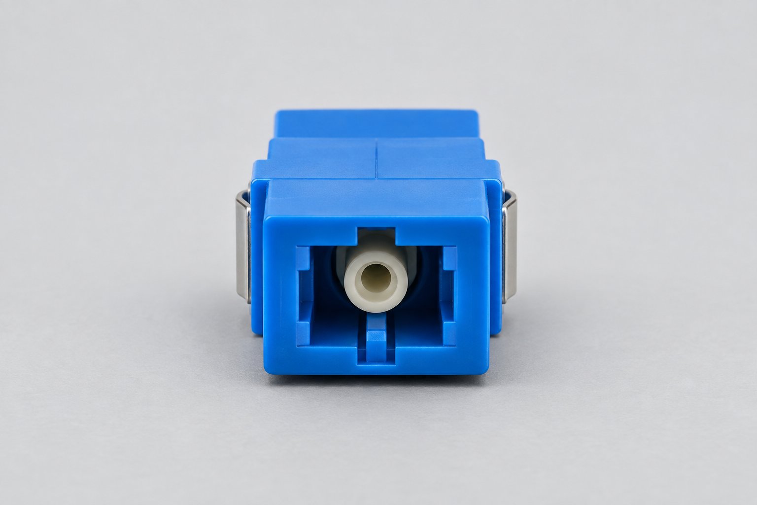
The alignment sleeve inside an adapter — visible here on a blue SC/UPC single mode adapter — is the surface contamination transfers to. Cleaning the adapter side of every mated pair is part of the standard, not an optional extra.
Building Inspection and Cleaning into Routine Maintenance
A one-off cleaning at commissioning protects nothing for long, because contamination is a continuous process. What protects the network is a program with defined triggers, defined owners and defined records.
Triggers. Inspect and, if needed, clean: before every first-time mating; every time a connector is re-mated after being unplugged; whenever a panel or enclosure is opened; whenever received power at a port drifts below its recorded baseline; and as part of every scheduled maintenance window on high-density panels where troubleshooting is expensive. Two categories deserve priority: ports with frequent re-patching (cross-connect fields, lab and staging areas), and any port that has already produced an intermittent fault.
Baseline records. When a link is accepted, record its measured insertion loss or received power. A contamination fault announces itself as drift from that baseline, and drift trends distinguish "the link is degrading, schedule a cleaning" from "the link just failed." Sites that keep per-port baselines isolate faults in minutes; sites that do not re-measure everything on every visit. The measurement methods and budget arithmetic behind those baselines are covered in our guide to fiber optic link loss budgets, and the acceptance-test procedure that produces them in our guide to OTDR acceptance testing.
Ownership and kits. Assign the inspection-and-clean procedure to the same role that owns moves, adds and changes on each site, and stock the kit at the site rather than in a vehicle: two one-click cleaners (2.5 mm and 1.25 mm), adapter-port cleaners, lint-free wipes, optical solvent, foam swabs, and an inspection scope. A kit that is not in the room does not get used, and a procedure that depends on carrying equipment between floors quietly stops being followed.
Records per visit. Log the date, panel and port, the condition found (pass / contamination cleaned / defect found), and any component replaced. Three benefits follow: you build a contamination map of the building that shows which locations need shorter cycles; you create an auditable trail for customers who require maintenance documentation; and you catch the panels whose sleeves keep failing inspection — those are the panels where adapters, not jumpers, are the consumable.
When Cleaning Is Not Enough: Adapter Wear and End-Face Damage
Some findings cannot be wiped away, and a maintenance procedure needs an explicit decision path for them.
Scratches across the contact zone. A scratch visible under the scope in the core or cladding contact zone — especially one that survives a clean — is permanent. The connector must be re-terminated or the assembly replaced. Repeatedly cleaning and re-mating a scratched ferrule does not improve it, and the debris it sheds makes the mating sleeve worse.
Worn or contaminated sleeves. Adapters are mechanical consumables. Their sleeves lose spring character and accumulate compacted contamination over hundreds and thousands of mating cycles. When a port fails inspection after cleaning, or produces high loss with every jumper mated into it while the jumpers themselves pass, replace the adapter. They are inexpensive relative to the troubleshooting cost of leaving them in place, and swapping one is a minutes-long task on a labeled panel. Specifying adapters with a defined mating-cycle rating — for example the 500-mating-cycle rating carried by Nexora's LC/APC and SC/UPC adapter families (typical specification value; confirm against the product data sheet) — gives the replacement decision a measurable trigger instead of a guess.
Ferrule chips and cracks. A dropped or raked connector can chip the ceramic without any visible damage to the boot or housing. Chips near the contact zone shed debris with every mating. Any connector with a visible chip or crack in the ferrule is removed from service, not cleaned and returned.
Heat and burn damage. On high-power links, a contaminated contact point can burn — the optical power concentrates on the particle and pits the glass. This is rare in premises networks and a real consideration wherever higher optical powers run. Burned end faces are not recoverable; the connector and often the port it burned into require replacement.
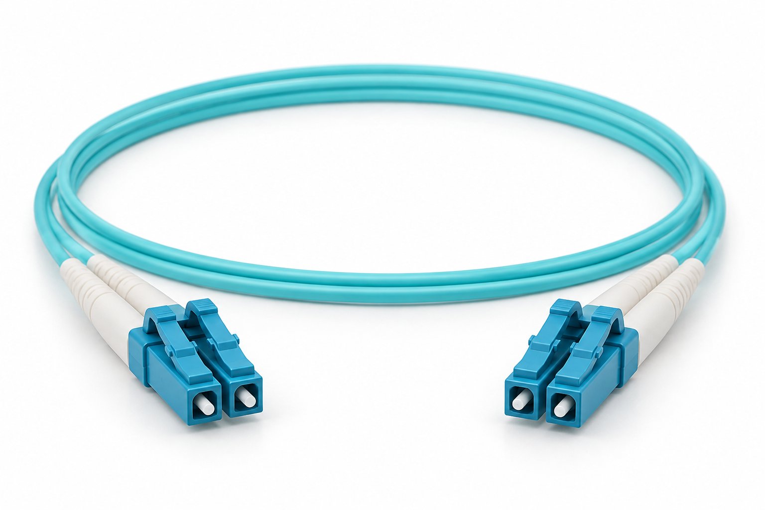
A duplex OM4 patch cord such as this LC-LC assembly carries two mated pairs per link — four end faces and two adapter sleeves per connection. Channel loss arithmetic must count every one of them, which is why per-cord release limits and clean mating discipline both matter.
Contamination, Loss Budgets, and Misleading Test Results
One reason contamination survives commissioning is that the common quick tests are the wrong instruments for finding it. A continuity check answers "is light reaching the other end" — and a connector carrying an extra 0.4 dB of contamination loss still passes it easily. A power-meter reading taken without a proper reference can absorb the extra loss into the link's apparent margin. Even an OTDR, the right tool for locating loss events along a run, has a dead zone at each connector where the reflection from the event itself masks the measurement immediately behind it. The result is a fault class that systematically hides from the tests that are actually run, and shows up later in the subscriber's experience instead.
The practical defenses are procedural rather than exotic. First, test links against a calculated loss budget — not against "the light came through" — so an extra mated-pair loss has nowhere to hide; our guide to calculating a fiber optic link loss budget walks through the arithmetic. Second, inspect end faces before measuring, because a measurement taken through contamination measures the contamination, and re-terminated or re-cleaned links must be re-measured afterward. Third, treat any measured value near the budget limit as an inspection trigger rather than a pass, since margin that exists only because of a dirty-but-lucky reading will not survive the next mating cycle.
It is also worth noting how factory quality control interacts with field contamination. Cords from a manufacturer that measures insertion loss and return loss on every assembly and inspects every end face before packing arrive with a measured baseline; incoming inspection then verifies transport and handling rather than re-adjudicating the product. Cords that arrive with unprotected ferrules, missing dust caps or no test records start the site's life with an unknown end-face condition, and every unknown is a fault discovered later. The upstream counterpart of this article's topic — how a manufacturer's pre-shipment checks interact with a buyer's incoming inspection — is covered in our overview of fiber optic product quality verification.
What to Check on the Supply Side
Cleaning and inspection discipline protects the network you already have. Product selection determines how much protection the components themselves contribute. When specifying adapters and patch cords for projects where maintenance access is expensive, the following checks matter:
| Component factor | What to verify | Why it matters for maintenance |
|---|---|---|
| Alignment sleeve material | Zirconia ceramic split sleeve, bore concentricity | Sleeve quality decides whether geometry survives hundreds of mating cycles |
| Mating cycle rating | Stated durability figure (e.g. 500 mating cycles as specified on Nexora adapter data sheets — confirm per product) | Gives adapter replacement a measurable trigger |
| Optical limits | Insertion and return loss stated per mated pair as typical values | Adapters: ≤0.20 dB typical insertion loss in Nexora's LC/APC and SC/UPC families; cords: per-cord release limits (e.g. ≤0.5 dB per cord on SC-SC single mode, ≤0.3 dB per cord on LC-LC OM4 duplex, typical values across production) |
| Polish type clarity | UPC and APC versions clearly separated; adapters match connector polish | A polish mismatch is unfixable in the field and often discovered during, not before, installation |
| Pre-shipment inspection | End-face inspection plus loss measurement on every cord before packing | Incoming inspection verifies handling rather than product quality |
| Packing protection | Dust caps fitted, anti-static bags, protected ferrules in transit | Contamination that starts in the carton is contamination on your first mating |
| Documentation | Test records per cord or batch on request | Gives acceptance testing a baseline and claims a reference point |
| Warranty | 12 months from shipment date as standard on Nexora fiber optic products | Defines the window in which manufacturing defects are handled with the supplier |
The insertion and return loss figures quoted above are typical reference values for standard configurations — not guaranteed limits for every sleeve, ferrule and length combination. Pin the values that matter for your link budget to the product data sheet for the specific configuration you are ordering, and confirm the measurement wavelengths: 1310/1550 nm for single mode assemblies, 850/1300 nm for the multimode OM4 family. Our guides to choosing patch cords and adapters and to reading patch cord specifications cover how these figures are measured and how to compare them between suppliers.
Frequently Asked Questions
How often should fiber optic connectors be cleaned?
Clean on triggers, not on a calendar: before first mating, after any unplugging, whenever a panel is opened, and whenever measured power drifts below the recorded baseline. In practice a connector that is only mated once, into a verified-clean adapter, and left in service rarely needs maintenance cleaning; the re-patch points in a cross-connect field are where the cycle repeats.
Can I clean a fiber connector with isopropyl alcohol?
Only if it is a sealed, optical-grade formulation intended for fiber end faces. Bottled IPA from general stock is frequently water-contaminated, evaporates slowly and leaves residue. A dry one-click clean solves most contamination without solvent at all; reserve solvent wipes for oils and dried residue.
How many times can a connector be re-mated?
Connector specifications commonly allow hundreds of mating cycles, and adapters are typically rated around 500 cycles (typical specification value — confirm on the specific product's data sheet). Cycle ratings assume clean mating every time; a connector re-mated repeatedly through contamination consumes far more of its real service life than the counter suggests.
What magnification do I need to inspect a fiber end face?
Use at least 200× to identify contamination and damage, and 400× when evaluating against formal acceptance criteria. Video probes integrated with automated pass/fail analysis against IEC 61300-3-35 give the most consistent results and produce inspection records as a by-product.
The link passed commissioning but errors appear under load. Is that contamination?
It is a classic contamination signature — loss that rises with receiver margin thinning under load — but not the only one. Inspect both sides of the suspect connection first, because it is the fastest check; if the end faces are clean, move to baseline comparison and a proper loss measurement before considering transceiver or bend issues.
How do I clean the adapter port on a live panel?
Use a one-click cleaner designed for adapter bulkheads, sized to the sleeve (2.5 mm for SC/FC/ST, 1.25 mm for LC), so the cleaning tip reaches the sleeve without dismounting the adapter where the panel design allows. Where an adapter must be replaced, do it in a maintenance window, label the panel correctly, and log the swap so port history stays accurate.
Do dust caps really matter if the connector is going straight in?
Yes — they matter most in exactly that moment. A cap keeps settling dust and accidental touches off the ferrule between manufacture and mating. The cap comes off when the connector is inspected, and goes back on if mating is interrupted for any reason.
What should I do with a connector that fails inspection twice after cleaning?
Stop cleaning and replace or re-terminate it. A defect that survives two cleaning cycles is almost always physical damage — a scratch, chip or crack — and continued cleaning risks carrying debris into the mating sleeve.
A Field-Ready Maintenance Kit Checklist
Programs fail on logistics before they fail on technique. The kit below fits in a single case, covers every connector type in a typical structured cabling plant, and costs less than one avoidable emergency call-out. Check the kit itself on a schedule: cleaning tape runs out, solvent pens dry, and a depleted kit teaches the team to improvise.
- Inspection scope — 200× minimum for field checks, 400× capability for acceptance work; video probe preferred so results are displayed and recorded, not squinted at through an eyepiece.
- One-click cleaner, 2.5 mm — for SC, FC and ST ferrules and for the bulkhead side where a dedicated port cleaner is not used.
- One-click cleaner, 1.25 mm — for LC and MU ferrules; this is the one that runs out first, because LC dominates modern panels.
- Adapter port cleaners — sized to the sleeve for SC and LC bulkheads, so the adapter side of the interface can be cleaned without dismounting hardware.
- Lint-free wipes — sealed packs; a box left open in a dusty room contaminates itself.
- Optical-grade solvent — sealed pens or bottles formulated for fiber end faces, never decanted into an open container at the site.
- Foam cleaning swabs — for recessed sleeves and spot work where a wipe cannot reach.
- Spare dust caps and port plugs — because the cheapest way to keep an end face clean is the cap it came with, and caps are the first thing lost in a work area.
- A short laminated procedure card — the inspect-clean-inspect sequence, the handling rules and the escalation path to adapter replacement, so any technician on the site executes the same steps.
Two inventory rules keep the kit trustworthy. First, anything opened, dropped or suspected of contact with a ferrule is either re-capped and re-inspected or discarded — nobody re-tests a suspect wipe to save a cent. Second, restock on a count, not on failure: when the 1.25 mm cleaner or the solvent pen goes below its spare, it goes on the order list the same week. A maintenance program is only as reliable as the boring logistics behind it, and the kit is where that reliability lives.
Key Takeaways
- Contamination at the mated interface is the most common, most preventable cause of fiber link degradation — and the fault class most likely to pass a quick commissioning check and surface later.
- The professional sequence is always inspect, clean if needed, inspect again — on both sides of every mated pair, connector and adapter sleeve alike.
- Dry-clean first with a one-click tool; escalate to optical-grade solvent only when dry cleaning fails; never re-use a cleaning surface; never blow on an end face.
- Adapters and sleeves are consumables: track mating cycles, replace ports that stay dirty, and log per-port baselines so drift is visible before it becomes an outage.
- Specify components that arrive clean and measured: dust caps fitted, end faces inspected, per-cord loss limits stated as typical values with data sheets to confirm, and a 12-month warranty from shipment date as the standard commercial baseline.
Keeping mated connections inside budget is a combination of two disciplines: a maintenance routine your team actually follows, and components specified so that clean, low-loss mating is the factory default rather than the field repair. If you are planning a new build or standardizing connectivity across sites, tell us your connector types, polish requirements and expected mating frequency — our team at Nexora will help you match adapters and patch cords to the maintenance reality of your network, with test records and packing protection specified from the first carton.