
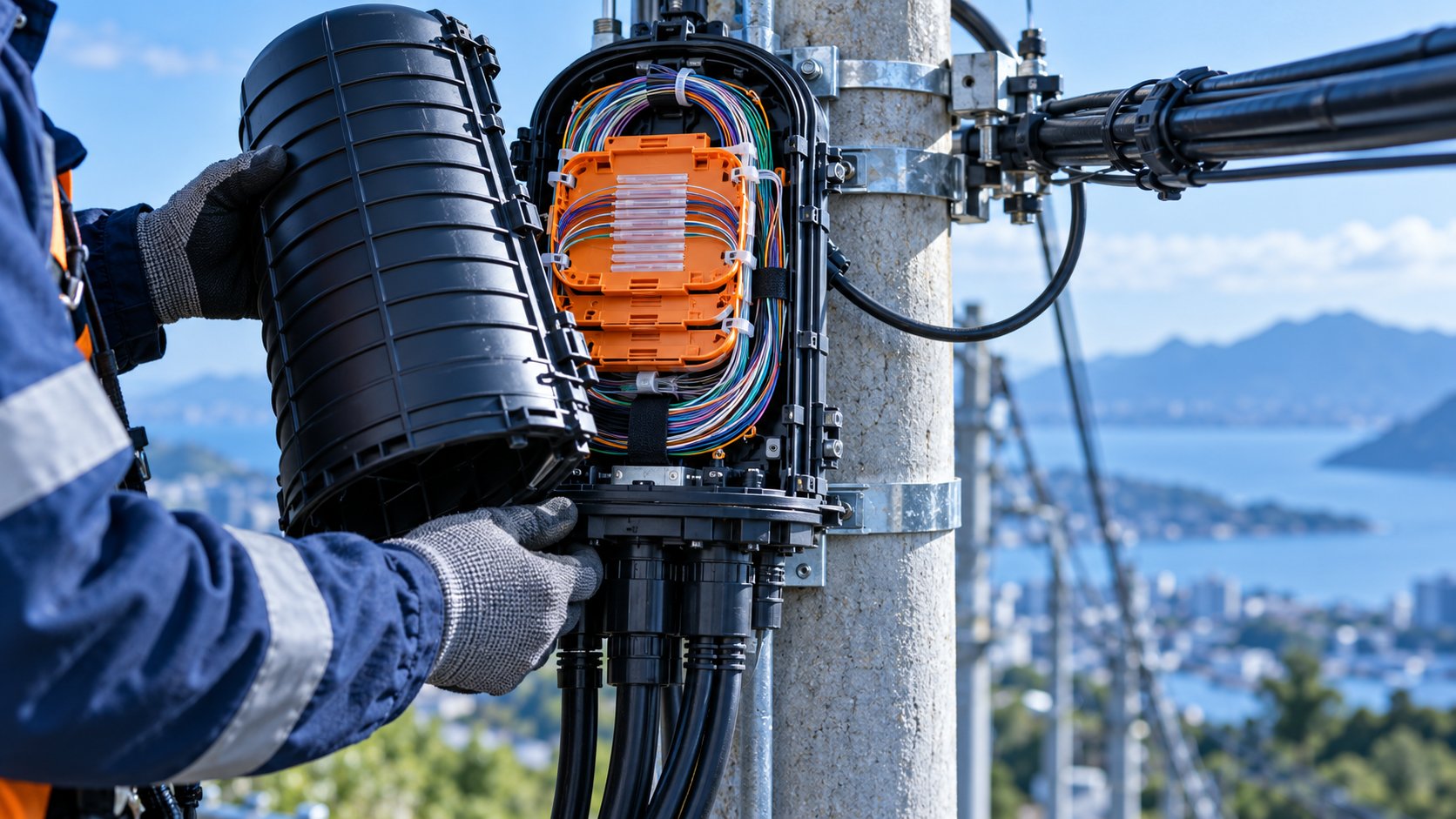
A buyer's guide to choosing fiber optic splice closures and managing slack storage: dome vs inline, ports, sealing, bend radius, installation and failure prevention.
Few parts of an outside-plant route expose every single fiber to human hands at once. A splice closure does. At each splice point along the route, the technician opens the closure, strips back cable sheaths, handles loose tubes, splices 24, 96, sometimes 288 fibers, and closes everything back up with the expectation that nobody will open it again for years. Every other element in the chain — the cable, the connectors, the patch panels — is engineered at the factory. The closure is assembled in the field, in whatever weather the schedule allows, by whoever is on the crew that day.
That is why closure failures rarely show up at handover. They show up months later. Water finds a gasket that was seated wrong. Loss creeps up on a fiber that was coiled tighter than it should have been. A re-entry that should have taken 40 minutes turns into a day of troubleshooting because the first crew routed the buffer tubes so nothing can be reached without disturbing live splices. For a contractor or network operator, the closure decision is not a small line item on the BOM. It is a decision about how much your network will cost to touch again. This guide walks through what a closure actually has to do, how to specify one, and how slack storage inside it determines long-term reliability — written for the person who signs the purchase order.
What a Fiber Optic Splice Closure Actually Has to Do
The Four Jobs
Strip away the datasheets and marketing, and a splice closure has exactly four jobs. Every feature you evaluate should map back to one of them.
Job 1: Keep water and dirt off the splices. A fusion splice protected by a heat-shrink splice protector is not waterproof on its own. The closure's entire sealing system — dome gasket, cable entry seals, and the seals around any test ports or valves — exists to keep the inside dry for the life of the route. When water gets in, it does not usually kill a splice outright. It wicks along fibers and buffer tubes, and over months it causes attenuation to drift upward. By the time someone measures it, the damage is spread across dozens of fibers and tracing the cause is miserable work. Buyers should ask the closure supplier specifically how each cable entry is sealed — heat-shrink seals, mechanical compression seals, or gel seals — and how many entries the closure supports, because a closure with fewer entries than your design needs forces improvised sealing, which is where leaks start.
Job 2: Store slack at a safe bend radius. Loose-tube cable is forgiving in a straight line and unforgiving in a tight coil. Industry guidance typically puts the minimum bend radius for outdoor loose-tube cable at 20 times the cable diameter during installation and 10 times in service — confirm against the manufacturer's datasheet for the exact cable you are deploying. Inside a closure, the fibers themselves (after tube breakout) are even more delicate. The splice trays and storage baskets inside the closure have to hold both the excess cable length and the coiled slack fibers at radii that will not stress them. A closure with generous, well-organized trays makes a good splicer look great. A cramped one makes every crew fight for space, and the fibers pay for it.
Job 3: Allow future re-entry without killing fibers. This is the job most often ignored at purchase time and most expensive to get wrong. Routes change. A new subscriber is added, a fiber is cut by excavation, a splitter needs to go in mid-route. Every one of those events means reopening the closure. A closure designed for re-entry lets a technician open the dome, reach a specific splice tray, and work on one fiber without disturbing the rest. A poorly designed one forces the crew to uncoil everything, flex stored fibers repeatedly, and risk breaking splices that were fine. Ask the supplier how many re-entries the closure is rated for and how the trays and fiber routing behave when the dome is off. Reputable manufacturers can answer this without hesitation.
Job 4: Survive the environment it is mounted in. A closure bolted to a pole at height deals with UV, temperature cycling, and vibration. One buried in a handhole deals with groundwater, soil pressure, and the mechanical load of being dug around. A pedestal-mounted unit deals with condensation from daily temperature swings. The closure body material, gasket material, and sealing method all need to match the mounting environment — and the buyer should match them deliberately, not assume one SKU covers everything. Ask for the operating temperature range and sealing ratings on the datasheet and put them in the purchase specification, not just in an email thread.
Where Closures Sit in a Real Route
Closures appear at every point where two cable sections are joined. In practice that means several distinct mounting situations on a single route, and the closure type should follow the situation.
On an aerial route, the closure hangs on the messenger wire or is attached to the pole, sometimes with the cable looped to take up thermal expansion. The closure and its mounts need to handle wind and ice loading, and the slack storage has to stay organized when the closure swings.
On a direct-buried route, the closure goes into a buried handhole or vault, or is direct-buried inside a protective housing. Access means opening ground, so re-entry design matters enormously — every reopening is a crew, a truck, and a permit.
On a duct route, the closure sits in a manhole or at the duct access point. Space is usually tight, water in the manhole is common, and the closure's sealing system gets tested by humidity and standing water even when it is doing its job.
In a pedestal or vault, the closure sits above or below grade with the cables entering from below. Condensation management and gasket quality decide whether the inside stays dry.
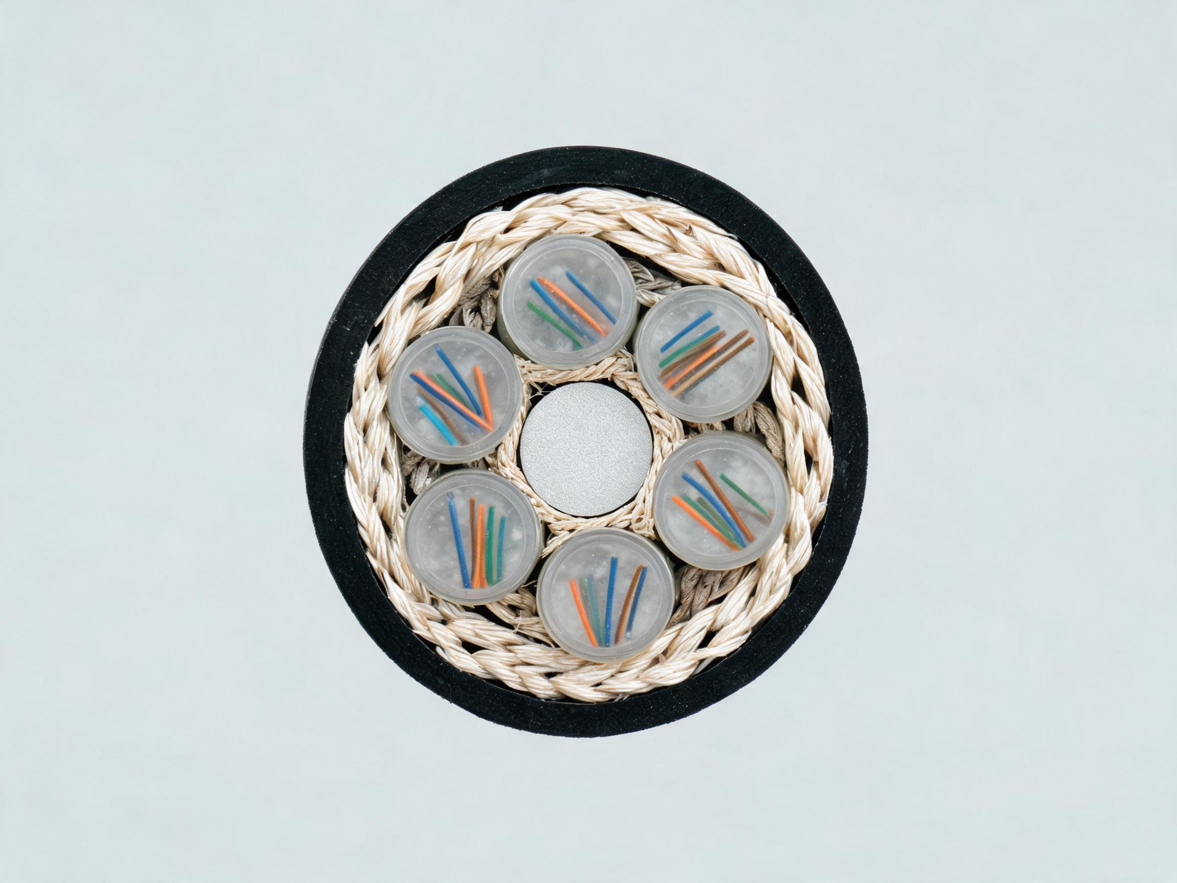
The common thread: routes built on loose-tube outdoor cable, such as Nexora's Outdoor G.652D Single Mode Fiber Optic Cable, rely on a properly specified closure at every splice point. That cable — available in 2 to 288 cores, gel-filled loose tube, with steel wire or FRP strength member and black PE jacket — arrives on drums of 2, 4, or 6 km. Every drum change on the route is a splice point, and every splice point is a closure. A 40 km route built from 4 km drums means nine closure decisions before the first shovel goes in the ground. Add mid-span access points for future branches, and the count goes up. The fibers that terminate inside those closures — pigtails and patch cords from suppliers such as Nexora, with SC/LC/FC connectors in UPC or APC polish — are only as reliable as the environment the closure maintains around them.
Why Buyers Should Care Before the Order, Not After Acceptance
The economics of closures are lopsided. The closure itself is a small fraction of the installed cost of a route — the labor to splice it, the cable around it, and the civil work to reach it dominate the budget. So when a closure underperforms, the repair cost is not "a new closure." It is a crew mobilization, traffic control or excavation where required, re-splicing time, and often emergency response on a live network with customers noticing loss. Rework on closures is dominated by labor and access, not parts.
This is also why loss problems in closures are hard to catch at handover unless you measure properly. A splice that is under stress inside a crowded tray can pass an initial test and drift within months. Acceptance testing with an OTDR, done at the right wavelength and with the right analysis, is how you catch over-tight slack storage and marginal splices before the crew leaves the site — see how to accept a new fiber installation with OTDR testing. But the better move is to prevent the problem at specification time: write the closure requirements — entry count, re-entry rating, tray capacity, sealing method, mounting hardware — into the purchase order, and verify them at delivery, not two years later at the first fault.
A buyer who spends an hour on closure specification can save hundreds of crew-hours over the life of the route. The next sections break down closure types, how to match a closure to your cable and environment, and how to design the slack storage inside so the next technician who opens it finds fibers that are healthy and easy to work with.
Dome or Inline: Matching the Closure Shape to the Route
The first decision on any closure specification is not brand or price. It is shape. Dome closures and inline closures solve different problems, and choosing the wrong one costs you either splice capacity or routing flexibility. Get this right before you look at a single datasheet.
A dome closure, sometimes called a vertical or hat closure, is a rounded canister. Cables enter from the bottom or lower sides, splices sit on trays stacked inside the dome, and slack coil sits around the splice trays or in dedicated baskets. The dome shape gives you a generous internal volume relative to its footprint. That volume is why domes dominate splice-heavy applications: a junction point where several cables meet, a splitter location in an FTTH distribution network, or a joint where a feeder cable branches into distribution cables. If the closure exists mainly to protect splices and the fibers mostly terminate there, a dome is usually the natural fit.
An inline closure, also called a horizontal closure, is a long cylinder. Cables enter at both ends, and fibers can pass straight through without being spliced. That through-path is the defining feature. On a long trunk route where a cable continues onward and only some fibers are dropped or spliced at a given point, the inline shape lets you route express fibers through the closure without breaking them. The elongated body also suits duct installations, where the closure lies in a handhole or vault alongside the duct run, and aerial builds where the closure hangs on the strand and cable continuity needs to follow a straight line.
A practical rule of thumb: if the point is a destination for splices, lean dome. If the point is a waypoint on a longer route, lean inline. In real networks you need both, and most contractors standardize on one or two sizes of each.
| Attribute | Dome closure (typical) | Inline closure (typical) |
|---|---|---|
| Shape and orientation | Rounded canister, installed vertically (hat-style) | Elongated cylinder, installed horizontally |
| Typical mounting | Buried in a handhole or vault, pole-mounted, or wall-mounted | In duct vaults, handholes, on aerial strand, or direct-buried |
| Best-suited routes | Splice-heavy junctions, FTTH splitter points, branch points, feeder-to-distribution transitions | Through-route trunk and backbone sections, express-fiber pass-throughs, long span joints |
| Cable entry pattern | Entries concentrated at the base or lower ports on multiple sides | Entries at both ends, aligned with the cable route |
| Slack storage style | Coils stored around stacked splice trays or in internal baskets; large relative volume | Coils stored in trays along the body length; slack for express fibers routed through dedicated storage |
| Re-entry behaviour | Full reopen to access any splice; often more internal working room once opened | Can access one end or one tray section without disturbing the far-end seal, depending on design |
All values in that table are typical of the product categories, specifications subject to datasheet. Confirm entry counts, internal dimensions, and re-entry design against the specific manufacturer's datasheet before you commit to a model.
Port Count and Cable Entries: Count What You Will Actually Have
Port count is where buyers get burned. The port count is the number of cable entry openings in the closure body, and every one of them matters. Count four things: cables entering now, any looped or dummy cables (a cable that enters and exits the same closure, common on through routes), planned future cables, and a spare allowance for the unexpected.
Worked example. A distribution point today takes one 96-core feeder in and three 24-core distribution cables out. That is four cables, four ports. You plan one more distribution cable in year two: five ports. Loop the feeder as a dummy cable for future flexibility? That can consume a second port. Suddenly you need six or seven ports, and you have not added a single unplanned repair cable. This is why contractors routinely under-specify. They count today's cables and forget that a closure lives in the ground for twenty years while the network around it grows. A sealed unused port is cheap at order time and expensive to retrofit later. As a habit, add at least one to two spare ports beyond your calculated need, and confirm unused ports come with plugs or blank seals that maintain the closure's ingress rating.
Also check that the port sizes accommodate your actual cable diameters and that the sealing hardware matches. A 288-core cable and a 12-core drop cable need very different port grommets, and mixing sizes on one closure means ordering the right gland set for each. If your route includes direct-buried spans, size the entries for the armored cable you actually installed — our guide on when to use armored fiber optic cable covers which outdoor and industrial routes demand it.
Sealing Methods at a Glance
Closures seal at two places: the cable entries and the body joint. At the entries, you will typically encounter three methods, each a trade-off between skill, time, and reusability. Heat-shrink sealing uses adhesive-lined sleeves shrunk onto each cable entry. It gives a robust, permanent seal and is the traditional choice for buried closures, but it is single-use: re-entry means cutting and replacing the sleeves, so you must stock consumables in the field. Mechanical seals use compression grommets or gel-filled entry blocks tightened by bolts or a clamping plate. They install fast, tolerate a range of cable diameters with the right insert set, and can usually be reopened without replacing the sealing hardware, which is why they dominate on closures expected to be reopened. Sealing tape or wrap-around methods are the lightest option, common on smaller closures and simpler joints, quick to apply but generally the least forgiving if applied in cold, wet, or dusty field conditions.
At the body joint, expect either a long mechanical seal (gasket and clamp) or heat-shrink around the full circumference. The same logic applies: mechanical for re-enterable, heat-shrink for maximum permanence. Whatever the method, the manufacturer's installation procedure and torque or shrink-temperature requirements govern the result — specifications subject to datasheet, and crew training matters as much as the seal design itself.
Re-entry and Why It Decides Total Cost of Ownership
A closure is not a one-time event. Routes get re-routed, cables get cut by other utilities, fibers get reassigned, splitters get upgraded. Every one of those events means reopening the closure. This is where the dome-versus-inline and seal-versus-seal choices compound into real cost.
Re-entry cost has three parts. First, consumables: a heat-shrink-sealed closure consumes new sleeves and possibly a new body seal at every opening, while a mechanical design typically reuses its seals. If a route expects two or three re-entries over its life, the consumable and labor delta between seal types can exceed the original price difference between closure models. Second, labor and risk: every reopening exposes splices and slack to mishandling. A closure with well-organized slack baskets and removable trays lets a tech work one section without disturbing the rest; a cramped interior forces them to lift coils and risk bend-radius violations on live fibers. Third, network exposure: the longer and harder the reopen, the longer your fibers sit in an open, unsealed environment on a live route.
So when you compare closures, do not compare purchase prices. Compare purchase price plus expected number of re-entries times the per-entry cost of consumables and labor, weighted by the route's likelihood of change. A slightly dearer mechanical-seal inline closure on a trunk route that will see splitter upgrades and repairs will usually win over its lifetime. A cheap heat-shrink dome on a quiet branch splice that will never be touched again is perfectly reasonable. Match the closure to how often you expect to open it, not just to what goes inside it on day one.
One last note on what goes inside: splices in any closure are only as good as the pigtails and cable fibers they join. Nexora supplies outdoor G.652D loose-tube cable and SC/LC/FC pigtails with insertion loss ≤0.3 dB typical and return loss ≥50 dB UPC / ≥60 dB APC, so the fibers your crews dress into the dome or inline trays meet the loss budget you designed the route around. The closure supplier protects the joint; the cable and pigtail quality determines what the joint is worth protecting.
Slack Storage and Loop Management: The Rules That Protect the Fiber
Every splice you make is a liability you will revisit. Fiber breaks, routes get rerouted, networks get split. If the slack inside your closure is coiled cleanly, organized and labeled, a repair takes twenty minutes. If it is a crushed bird's nest under the dome, you are re-splicing half the closure and blaming whoever dressed it. This section covers the storage rules that separate a closure that lasts twenty years from one that generates truck rolls.
Why Slack Exists at All
Slack is stored fiber, deliberately left inside or near a splice closure, and it serves four jobs. First, re-splicing without re-pulling. Every splice consumes fiber. A mechanical splice or fusion splice consumes roughly 40 to 60 mm of fiber each time you cut back and re-join, and a bad splice may need two or three retries. Without stored slack, your second retry forces you to pull a new cable section back from the last closure. With slack, you open the tray and work.
Second, future splits. On an FTTH feeder or a distribution route, a closure that today joins two cables may in three years host a branch drop or a splitter. Stored slack lets a crew split the fiber at that point without excavating or re-hanging a span. Third, thermal movement. Aerial cable expands and contracts; buried cable shifts with frost heave and soil settling. Slack inside the closure absorbs that movement so it does not translate into tensile stress on the splice itself. Fourth, repair margins. When a vehicle takes down a pole or a backhoe finds your duct, the repair section between two closures needs slack at both ends to make the new splices. The closure loops are that margin.
How Much Slack to Store
The common rule of thumb is to store roughly 1.5 to 2.5 meters of slack per splice point, then add route-specific allowances for the span between closures. Treat those numbers as typical field practice, and confirm the final quantities against the project specification and the closure manufacturer's datasheet, because tray geometry and dome size set a hard ceiling on what you can actually store.
Typical allowances by route type, for planning purposes only:
| Route type | Typical slack per closure | Notes |
|---|---|---|
| Aerial span | 2-3 m plus a pole loop of 15-20 m at designated poles | Pole loops absorb repair events; see the aerial section below |
| Direct-buried | 2.5-4 m per closure, extra 10-15 m per km at fault-prone crossings | Repair splices need generous cut-back margins |
| Duct | 2-3 m per closure | Handhole/manhole closures constrain loop size; check tray capacity |
| Building entry | 1.5-2 m per closure or terminal box | Tight cabinets; prioritize bend radius over extra length |
Whatever number you land on, write it into the method statement and check it at acceptance. Slack that exists only in the contractor's imagination cannot be re-spliced.
Bend Radius: The One Number That Decides Fiber Life
Bend radius is where slack storage fails quietly. Pull a loop too tight today and the optical loss may be negligible. Six months of thermal cycling and vibration later, that microbend shows up as a loss spike or a marginal return-loss reading, and you will spend hours in a manhole finding it.
The governing rule is diameter-based. For Nexora's outdoor G.652D cable, the minimum bend radius is 20 times cable diameter during installation and 10 times cable diameter in service, per the product specifications. A 24-core cable at roughly 12 mm diameter, for example, therefore wants no tighter than about 240 mm while you are pulling it and 120 mm once it is at rest. Confirm your exact cable diameter and figures against the manufacturer's datasheet before you set tray coiling diameters. Note the asymmetry: slack stored in a closure is in-service fiber, but the moment a technician pulls a loop out to re-splice it, the loop is being handled, and it must respect the installation radius while it is out of the tray.
Coiling method matters as much as the number. Store loops in flat, single-layer coils with each turn lying beside the previous one, or in a figure-eight pattern where the tray design calls for it and you need to pay fiber out from both ends without introducing twist. Never coil loose fiber into a stack of overlapping rings; the weight of upper turns crushes the lower ones against the tray wall. And never use standard zip ties or metal fasteners directly on fiber or on the 250 µm buffered fiber inside a loose tube. A zip tie pulled tight applies crushing force in a 2 mm line. Use hook-and-loop fasteners, or tie-downs designed for fiber with a broad contact surface and a defined breakaway tension. A tight tie is the single most common cause of latent microbend loss we hear about from field crews.
Organizing Loops Inside the Closure
Inside the closure, structure beats volume. A big dome stuffed with unmanaged slack is worse than a small one with disciplined dressing. Work through these elements:
- Splice trays/organizers. Each tray holds a fixed number of splices (commonly 6, 12 or 24 per tray, per the closure datasheet) with grooved guides for storing splice protectors and excess fiber in a controlled coil diameter. Fill trays in order and do not exceed the stated splice count.
- Storage baskets. Larger closures include a basket or stacking tray system for bulk slack between the port entry and the splice trays. Coil slack here in flat layers, in one direction, at or above the in-service bend radius.
- Strain relief on the tube. The loose tube entering the tray must be clamped so that tensile load on the cable stops at the clamp, not at the splice. Leave enough tube length inside the tray for a splice re-access, and secure the tube with the closure's supplied grommets or clamps, not improvised wraps.
- Dressing for re-access. Dress so that any single splice can be reached without disturbing its neighbors. That means slack routed in individual, identifiable paths to each splice position, not one shared bundle. When tray 2 of 5 needs a re-splice, the crew should be able to open tray 2 only.
Label everything: cable IDs, fiber counts, tray positions, and which slack length belongs to which route side. Labeling costs minutes at installation and saves hours at every future visit.
Aerial Slack Loops
On aerial routes the slack question splits into two locations: the loop at the pole and the storage inside the closure. A pole loop is a deliberate overlength of cable, typically 15 to 20 meters as a planning figure, coiled and lashed at a designated pole so a future repair or span rebuild can be made without pulling new cable. These loops sit on the strand or on a storage bracket, exposed to wind, ice loading and UV.
The closure itself stores the working slack: the fiber needed for the splices inside plus enough extra to reach the pole loop's cable end when it is finally used. Whether you keep additional fiber coiled inside the closure or rely on the pole loop depends on the network design; many operators do both, keeping repair slack on the pole where it is easy to reach and keeping splice-consumption slack in the closure where it is protected.
Wind and ice change the calculus. An aerial closure hanging on a strand moves. Every gust flexes the cable entries and, if slack is poorly stored, flexes the fiber at a fixed point inside the dome. Loops must therefore be secured inside the closure so no fiber sits under bending stress at a single point, and cable entries must use the closure's specified seals and strength-member clamps so strand movement loads the clamps, not the splice trays. Ice loading adds weight and shortens the strand, which pulls slack through the entries; the stored loops absorb that take-up. For choosing the cable that survives this environment, see our guide on how to choose and deploy figure-8 self-supporting fiber optic cable, and for all-dielectric self-supporting designs, our article on whether ADSS fiber optic cable is the right choice for your aerial network.
Common Slack-Storage Mistakes
These five failures account for most slack-related rework we see reported by contractor customers:
- Overlong loops crushed under the dome. The crew stores 6 meters where the tray holds 2.5. The dome closes on excess fiber, which crushes against the tray wall or the dome shell. Loss may test fine on day one and fail within a year. Store the specified length or upsize the closure; never overfill.
- Loops tied with metal fasteners or standard zip ties. As covered above, point-load crushing on buffered fiber creates latent microbends. Use hook-and-loop or fiber-rated ties only, and photograph the dressed tray before closing.
- Mixing express fibers with splice fibers in one tray. Through-routed (express) fibers that are not being spliced belong in their own guided path or dedicated tray section, clearly separated from active splices. When a crew opens the tray for a splice and finds express fibers woven through it, the odds of disturbing and breaking a live through-fiber are high.
- No labeling. An unlabeled closure forces the next crew to trace every fiber before touching anything. Label both cable entries and tray positions, and keep a route record that matches.
- Slack stored below in-service bend radius. A tray rated for larger-diameter cable cannot take a 288-core cable's loops at the same coil diameter. Check the tray's minimum coiling diameter against your actual cable diameter before ordering, and confirm with the closure supplier's datasheet.
Slack storage is not glamorous work, but it is the discipline that determines whether a closure is a twenty-year asset or a recurring service call. Specify the slack quantities, check the bend radius against the actual cable, dress for re-access, and document what you did. The fiber inside those loops, whether it is Nexora G.652D outdoor cable or pigtails terminating on the tray, will hold its specified attenuation and return-loss performance as long as the mechanics around it hold theirs.
Installing, Splicing and Sealing the Closure Step by Step
A splice closure is only as good as the crew's discipline on installation day. Most water ingress failures traced back to closures come from rushed preparation: rough sheath removal, unterminated armor, fibers pinched under a dome, or a sealant seated on a dirty cable jacket. The workflow below is the sequence experienced crews follow. Torque values, sealant compression figures, and re-entry limits vary between closures, so treat all numbers in this section as typical field practice and confirm each against the closure manufacturer's datasheet before your crew starts.
- Prepare the site and mounting. Stage the closure, splice trays, entry grommets, and tools where the work happens. If you are working at height or in a vault, confirm the mounting bracket, strand hardware, and bonding hardware are on the truck before you cut any cable. A closure opened twice because someone forgot a grounding kit is a closure with a compromised seal.
- Prep the cable entries. Slide all sealing components — grommets, heat-shrink sleeves, or mechanical seals — onto the cable before you strip anything. Every closure type has its own stack-up; get it wrong and you are re-seating a seal with fibers already spliced. Where armored cable enters the closure, bond and ground the armor per typical practice and local codes, using the closure's grounding lug or an external bond point. An unbonded metallic member is a fault hazard and, in some builds, a spec non-compliance.
- Remove the sheath and prepare tubes. Strip back the outer jacket to the length the datasheet specifies — typically enough to reach the tray with slack, not more. Clean the gel off the loose tubes with approved wipes, not rags that leave lint. Keep the strength member intact and trimmed to length; it anchors the cable, not the jacket alone.
- Fix the cables to the entry ports. Clamp the strength member to the closure's anchoring hardware and seal the jacket at the port. Pull-test by hand. The cable should take strain on the strength member, never on the tubes or fibers. Verify the bend radius at the entry respects the cable's minimum bend radius — for typical outdoor G.652D loose-tube cable, that is 20x cable diameter during installation and 10x in service, per the cable datasheet.
- Load the splice trays. Install the trays in the closure basket. Identify each tube, assign fiber positions, and mark the tray map before splicing. Crews that skip the map spend double the time troubleshooting later. Leave the trays accessible and check that the stored-fiber loops will clear the dome when closed.
- Fusion splicing. Splice in tube order, one tube and its assigned position at a time. Keep the splicer's electrodes clean and recalibrated — a dirty electrode shows up as high-loss splices you will chase for an hour. Target splices should be well under 0.1 dB typical; anything above roughly 0.1 dB gets re-spliced on a quality build.
- Install splice protection sleeves. Heat-shrink every splice immediately after splicing, centered over the fusion point, no bubbles, no exposed glass. A sleeve that shrinks off-center will crack under thermal cycling. Let sleeves cool before routing — a hot sleeve shoved into a tray holder deforms and loosens.
- Route fibers into storage. Coil the protected splices and slack fiber into the tray storage spools, respecting the tray's bend-radius posts. Do not exceed the tray's fiber capacity. Overloaded trays pinch fibers when the dome closes, and a pinched fiber is an OTDR mystery six months from now. For pigtails, route the 0.9 mm legs with gentle, even loops and no sharp transitions at the tray edge.
- Trial-close and test before final sealing. This is the step that saves callbacks. Close the dome loosely, without compressing the seal, and run your OTDR or insertion-loss check on every fiber. Verify no loss was introduced by routing. If anything reads high, reopen — now it costs minutes; after sealing, it costs a re-entry.
- Final sealing. With tests clean, torque the closure hardware to the datasheet's specified values in the specified pattern, typically crisscross rather than sequential. For heat-shrink seals, apply heat evenly per the datasheet. For mechanical or gel seals, verify full seating by sight and by the hardware's stop point. Note the re-entry torque or reuse limits if the closure may be reopened.
- Mount the closure. Hang or bolt the closure per its design — pole, wall, pedestal, strand, or vault mount. Aerial closures on strand must not carry cable strain; the cable's dead-load support and the closure suspension are separate functions. Leave service loops per the cable's bend radius rules.
- Label and document. Tag each entry with cable ID, fiber counts, and direction. Photograph the open tray before final closure and store the splice map. Field crews change; documentation does not.
Splicing inside the closure — factory-terminated pigtails vs field polishing
Almost every quality FTTH and transport build splices pigtails inside the closure rather than polishing connectors in the field. The reason is simple: a fusion splice to a factory-terminated pigtail gives you a connector quality that no field polishing kit can match consistently, especially on a bucket truck in the rain. The pigtail's factory connector is polished and tested under controlled conditions; the fusion splice itself, done by a competent technician with a good splicer, adds negligible loss. Field polishing puts connector quality at the mercy of the technician, the weather, and the consumables — and gives you no factory test record.
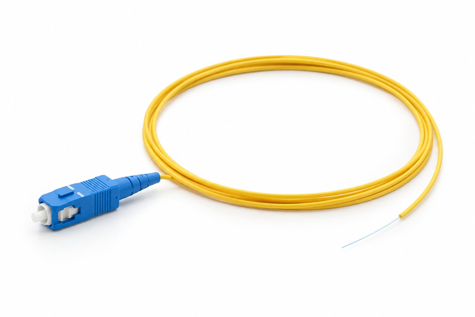
The typical build: incoming cable fibers are fusion-spliced to single-fiber pigtails, the splices are protected in sleeves and stored in the tray, and the pigtail connectors land on an adapter panel or stub port for later patching or direct connection. When you buy pigtails, specify and verify the parameters that matter. Nexora's Fiber Optic Pigtail line covers SC, LC and FC connectors in UPC and APC polish, with insertion loss of ≤0.3 dB typical and ≤0.5 dB max at 1310/1550 nm, and return loss of ≥50 dB for UPC and ≥60 dB for APC. They are available in G.652D single mode or OM3/OM4 multimode, with 0.9 mm tight-buffered LSZH or PVC jacket, in custom lengths from 0.5 to 30 m, MOQ 100 pcs per configuration. For an APC connector on an FTTH splitter or ODF port, the ≥60 dB return loss figure is what keeps reflectance out of your network; confirm test results on the pigtail datasheet rather than taking the label's word. The cables and pigtails that terminate inside the closure come from cable and patch cord manufacturers such as Nexora, while the closure itself comes from the closure supplier — check both datasheets before the installation date so entry port sizes match your cable diameters and tray layouts match your pigtail lengths.
Sealing quality checks before you walk away
Run a short, repeatable checklist at every closure before the crew leaves the site. First, a visual pass: sealant fully seated all the way around each entry, no jacket nicks at the ports, hardware at the torque stop, dome seating gap even. Second, a shake check — rock the closure gently and listen. Loose clamps, an unseated grommet, or a stray sleeve rattling in the basket should be caught now. Third, where the closure datasheet provides for it, a pressure or vacuum check of the sealed chamber as typical practice confirms the seal before burial or before the dome is closed for good; follow the datasheet's procedure and pressure values exactly, since over-pressurizing a closure can damage trays and fibers.
Then the test that actually matters: a final acceptance OTDR run on every fiber through the closure, at both working wavelengths for single mode — typically 1310 and 1550 nm. This catches splice loss, bends pinched under the dome, and crushed tubes introduced during routing. Do not rely on the pre-seal check alone; the final seal and mounting can introduce bends and stress that only show up on a trace taken after everything is torqued and hung. A proper acceptance trace baseline at handover is also your reference point for every fault-locate call for the next twenty years. For a full methodology — wavelengths, baselines, and bidirectional testing on new builds — see our guide on how to use an OTDR to accept a new fiber optic cable installation. Archive the traces with the splice map and closure photos.
Mounting options in one pass
Closures ship with or support several mounting families, and the right choice depends on the route environment, not the crew's preference. Confirm with the closure datasheet which hardware is included, which is optional, and what the mounting hardware torque and grounding provisions are — these are closure-specific items you verify with the closure supplier, not assumptions you make on site.
- Pole mount: bracket and banding to a wood or concrete pole. Common in FTTH distribution and drop aggregations. Check bracket load rating against closure weight with cables attached.
- Wall mount: buildings, shelters, and manhole entry walls. Confirm anchor type for the substrate — a concrete anchor spec is not a brick anchor spec.
- Pedestal mount: base-flange closures in above-grade pedestals. Verify the pedestal drain and that the closure's cable entries stay above any standing water line.
- Vault or handhole mount: below-grade closures need the correct environmental rating, and buoyancy and drainage become real design questions. Confirm the closure's submersion rating against the datasheet.
- Aerial on strand: suspension hardware carries the closure weight; the cable's own slack loop and strain management stay separate. Confirm strand-size compatibility of the suspension hardware.
Whatever the mount, grounding and bonding of metallic cable members is a task for the installation crew using the closure's grounding provisions — check that those provisions exist and are sized for your cable type before ordering. Get the mounting hardware, entry kit, and seal types specified in the bill of materials at purchase, not discovered on the truck. A closure ordered with the wrong entry kit for a 288-core cable is a schedule slip you bought yourself.
How Closures Fail, and What Prevents Each Failure
Most splice closures do not fail on day one. They fail quietly, over months, in ways that show up first as slow loss creep on an OTDR trace and end as a full outage on a feeder with no spare fibers left. If you understand the failure modes, you can specify against each one at the tender stage instead of paying for truck rolls later. The four failure modes below account for the large majority of closure-related problems we hear about from contractors, and every one of them can be prevented by decisions made before the closure is even ordered.
Water Ingress
Water inside a closure does three things over time. It degrades splice protection sleeves, it attacks any fiber surface where the coating has been nicked, and in freezing climates it turns into ice that crushes loose tubes and slack loops. The failure usually builds over six to eighteen months, which is why the symptom is loss creep on specific splices rather than a sudden break. An OTDR trace that shows a splice getting 0.2 dB worse each quarter is a wet closure until proven otherwise.
The causes are predictable. Poor port seals are the most common: half the ports in a domed closure left unoccupied and unplugged, or a round-port gasket jammed onto an oval cable jacket because nobody ordered the right reduction inserts. Wrong heat-shrink is the second cause. A heat-shrink seal sized for one cable diameter and closed over another leaves voids that pump water in on every temperature cycle, because air expands and contracts and drags moisture through the gap. The third cause is re-entry damage to the seal itself, which we cover separately below.
Prevention is procedural, not exotic. Require every unused port to be closed with the manufacturer's plug, not tape. Match the seal type to the cable at ordering time, and confirm the seal's accepted diameter range against the datasheet for the actual jacket you are buying. Ban re-entry on a closed closure unless a technician carries a documented seal kit and the manufacturer's resealing procedure. Specify closures with an IP rating appropriate to burial or aerial use and ask the closure supplier for the test conditions behind that rating. Finally, pressurized or gel-filled closures aside, always verify the closure is rated for the installation environment you actually have: a wall-mount box rated for indoor use on a pole will leak within one winter.
Microbending and Loss Creep from Bad Slack Storage
The second failure mode never involves water. It involves slack loops stored badly inside the tray. A fiber jammed under the dome when the closure is shut, a slack loop pinched between the tray edge and the cable, or a tie-wrap cinched down until the jacket deforms: all of these produce microbending. The loss shows up immediately at closure sign-off, or worse, it shows up months later when thermal cycling shifts the fiber a millimeter against the same pinch point.
The mechanics are simple. Single-mode fiber tolerates a bend radius of roughly 30 mm without measurable loss, but a fiber forced against a sharp tray corner or crushed under a tightened tie has an effective radius of a few millimeters at the contact point. At 1550 nm the attenuation from that contact can be 1 dB or more, and it fluctuates with temperature because the closure materials and the fiber expand at different rates. Contractors often chase this as a "bad splice" and re-splice it, which changes nothing, because the problem is in the storage, not the fusion.
Prevention starts at specification. Buy trays with a real bend-radius control feature: molded grooves, spindles, or covers that keep loops at diameter, not open tubs where fiber finds its own path. Use hook-and-loop ties in the tray and reserve tie-wraps for the cable itself, finger-tight only. Store slack in loops large enough to be handled, coil them so they lie flat, and never stack loops on top of each other so the upper coil presses the lower one against the tray floor. Before closing the dome, do the one check that catches almost every jam: close the lid slowly and look for any fiber, tube, or sleeve caught at the sealing plane, then shake the closed closure gently and retest if your contract allows it. A closure whose dome has to be forced down is a closure with something underneath it that should not be there.
Mechanical Damage
The third mode is external. Pedestal closures on suburban corners get hit by vehicles. Aerial closures on joint-use poles take falling branches, gunshots, and occasionally a bucket truck. Buried handhole closures take point loads from backhoes and from someone driving over the lid. None of this is preventable in the sense that you can stop traffic, but the damage pattern changes a lot with mounting choice.
An aerial closure on a span between poles is far less exposed than one mounted directly at a pole face where vehicles and ladder trucks interact with the pole. A pedestal in a fenced corner beats a pedestal at the curb line. In buried plant, a handhole with a rated lid under pavement is safer than a shallow direct-buried closure that the next excavator meets first. Where vandalism is a known problem, specify locking hardware and a closure shape that does not present a flat target. Also make sure the closure you pick is mechanically rated for the mount: an aerial closure must carry the cable's weight plus wind and ice loading through its mounting hardware, not through the cable itself. Confirm the mechanical and environmental ratings against the manufacturer's datasheet rather than assuming they exist.
One related point belongs here because it happens at installation, before any weather gets involved. Excessive pulling tension on the cable entering the closure, and tight bends at the port, put permanent micro-stress into the fiber that later combines with everything above. The pulling tension and bend radius limits for the cable itself are covered in detail in our guide to pulling fiber optic cable without exceeding tension and bend limits, and the same discipline applies at the last meter of the pull, where the cable meets the closure port.
Re-Entry Damage
Re-entry deserves its own heading because networks that survive their first five years almost always get reopened. New tenants need fibers, a splitter gets added, a damaged splice gets rebuilt. Every reopening is a chance to destroy the seal you installed correctly the first time.
The classic damage pattern: the technician cannot get the dome off, cuts the heat-shrink seal with a knife, re-closes with fresh shrink that does not bond to the old jacket surface, and the closure leaks from that day. Another pattern is fiber traps: slack looped near the sealing edge gets pinched between the dome and base when it is reassembled in a hurry, producing a fresh 3 dB event on a fiber that tested clean for years. A third is cable crush, where someone loosens the port clamp to "free up" the cable and never torques it back.
Prevention is a written re-entry plan. For networks you know will be upgraded, specify closures designed for re-entry, such as mechanical seals with reusable gaskets, rather than single-use heat-shrink, and pay the small premium. Keep the manufacturer's opening procedure and a spare seal kit with the closure records. Require the technician to photograph the tray layout before disturbing anything, and require a full bidirectional OTDR test of every fiber in the closure before it is resealed, not just the fiber being worked on. Retest after resealing too, because a newly pinched fiber is exactly the kind of defect a same-day test catches and a customer complaint does not.
A Short Maintenance and Inspection Checklist
For routine visits and fault audits, a short list done consistently beats an elaborate one done occasionally:
- Inspect the closure body, dome, and port seals for cracks, UV chalking, or evidence of animal damage before opening anything.
- Check that the closure is not holding water: a wet mounting bracket or staining around the base on a pedestal is a red flag.
- Confirm every unused port is sealed with a plug, not tape or a rag.
- Verify cable clamps and mounting hardware are tight and that cable weight is carried by the hardware, not by the fiber at the port.
- Check slack storage: loops at controlled diameter, hook-and-loop ties, no fiber at the sealing plane.
- Look for labeling: every port and splice identifiable without guesswork, because unlabeled splices turn a 20-minute job into a 4-hour one.
- Compare current OTDR traces against the as-built baseline for any fiber showing loss creep, and schedule a re-entry only with a seal kit on the truck.
- Update records after every visit, including photos, so the next technician reopens the closure with the same information you had.
None of this is complicated. It is specifying the right seal for the cable, buying trays that hold slack properly, choosing mounts that keep the closure out of the traffic path, and treating every reopening as a documented procedure. Do those four things and the closure stops being the weakest link in your plant. And when you are provisioning the cables and pigtails that terminate inside these closures, work with a manufacturer such as Nexora that supplies outdoor G.652D loose-tube cable and low-loss pigtails to consistent specifications, so the components inside the closure are as predictable as the closure itself.
Specifying and Sourcing a Splice Closure: A Buyer's Checklist
By this point in the guide you know what a closure does and how slack should be stored. What is left is the part that decides whether the network stays reliable for twenty years or starts leaking water in year three: how you write the specification, what you ask the supplier, and what you accept at handover. This section is written for the person who has to sign the purchase order.
One rule before the table. Closure manufacturers publish numbers that look reassuringly specific, but many of those numbers are typical claims rather than certified results for the exact unit in front of you. Everything below should be treated as typical values, specifications subject to datasheet. Where a datasheet does not state a test method, assume it was not tested and ask.
The specification line items that actually matter
Most closure failures trace back to five things: bad sealing, a tray that does not fit the fiber, a port entry that crushes the cable, brittle plastic, and hardware that arrives in the wrong box. The checklist below covers those. Anything not on this list, such as color or branding, is negotiable. Anything on this list, do not negotiate down.
| Line item | What to specify | What to confirm with the supplier |
|---|---|---|
| Port count and configuration | Number of round ports and oval/cut ports; enough for current build plus future laterals. Match to your cable diameters, e.g. 2–288 core feeder cables and smaller distribution drops. | Maximum and minimum cable diameter per port. Whether unused ports are pre-sealed plugs or must be ordered separately. Whether oval ports suit both round cable and flat drop cable. |
| IP / sealing class | IP68 is the common claim for dome and inline closures. Ask what it means for this specific model. | The test method behind the claim: was it submerged, at what depth, for how long, with cables installed? An IP68 rating on an empty housing proves nothing about a sealed closure with four cables entering it. |
| Re-entry count | How many times the closure can be reopened and resealed with the original seal kit before performance degrades. | Whether re-sealing uses the same heat-shrink or mechanical seal, whether spare seals are consumables, and whether the manufacturer states a documented re-entry limit rather than a vague "re-openable" claim. |
| Tray capacity and type | Splices per tray, trays per closure, and total capacity. Confirm the tray suits 250 µm spliced fibers with 900 µm or fan-out protection, not just bare fiber. | Capacity per fiber size: a tray that holds 24 splices of 250 µm may hold fewer with 900 µm pigtails coiled in. Slack loop length per tray and bend radius control in the tray. Whether trays are stackable and individually removable without disturbing others. |
| Material and UV stability | Modified PC or similar engineering plastic, UV-stabilized for outdoor exposure, with metal or reinforced load-bearing parts on inline closures. | UV test duration behind the claim. Whether the stated material applies to the gaskets and seals too, not just the shell. A rigid shell with a cheap gasket is a leak waiting for summer. |
| Temperature range | Typically -40 °C to +70 °C for outdoor telecom closures; this matches the operating range of the G.652D loose tube cables terminating inside. | Whether the sealing performance is rated across the full range or only at ambient. Confirm against the manufacturer's datasheet for the exact model. |
| Hardware kit and grounding | Complete kit for every installation scenario in your project: aerial, direct-buried, handhole, and pedestal mounting. Stress-control and clamping for each cable size. Grounding lug where armored or steel-strength-member cable is used. | Exactly which items are in the box, itemized. Which mounting brackets are optional extras. Whether the hardware suits your cable diameter range or is one-size-fits-most. |
Note: values above are industry-typical; specifications subject to datasheet. Confirm every figure against the manufacturer's datasheet for the specific model and batch.
Questions to put to the closure supplier
Write these into the RFQ. A supplier who answers them in writing is telling you the product was engineered. A supplier who answers "yes, all standard" to everything is telling you to keep looking.
- How many re-entries does the closure support with the same seal kit, and what is your test evidence? If the answer is "unlimited," ask what that is based on. Real closures have a practical limit set by the gasket or heat-shrink, and you want the number and the method.
- How was the IP rating tested — on a sealed closure with cables installed, or on the empty housing? Ask for the test report reference and the conditions: depth, duration, temperature cycling if any.
- What is the tray splice capacity for 250 µm fiber, and separately for 900 µm pigtails? Get both numbers. Your access network will use both, and the smaller number is the one that governs your design.
- Are spare seal kits, gaskets, trays, and port plugs available as spare parts for at least five years after purchase? A closure you cannot reseal in year four is a closure you are replacing in year four.
- What exactly is included in the mounting and hardware kit? Ask for the packing list per closure, and price any aerial or pedestal brackets that are sold separately so the comparison between quotes is honest.
- What is the packaging format, unit lead time, and minimum order? Individual cartons protect the shell in transit; bulk-packed closures arrive scratched and cracked. Ask whether trays are pre-installed or field-assembled, because field assembly adds minutes per closure across hundreds of closures.
The budget view: the closure is cheap, the rework is not
On a per-unit basis, a splice closure is a small line item next to the cable, the civil work, and the splicing labor. That is exactly why it is dangerous in a bid. When two quotes differ by a few dollars per closure, the cheaper one usually saves money on the seal, the tray, or the gasket — none of which show up until water does.
Now price the failure. Reopening a closure means a truck roll, two splicers or a splicer plus an assistant, traffic management if it is in a footway or chamber, and often a civil crew to lift the lid or excavate. In a live network it also means outage risk: every fiber in that closure is carried on a splice that gets handled. A closure reopened for water ingress is a closure where someone re-splices 48 or 96 fibers under time pressure. Compare that against the unit price difference and the specification decision makes itself.
The practical rule many contractors use: buy the closure to a written specification, buy spare seal kits at the same time, and never let the closure be the place you save the last two percent of project cost. Spend the scrutiny where the labor is, because labor is the part you pay for twice when something leaks.
Where Nexora fits in
Nexora does not manufacture splice closures, and this guide has not recommended one. What terminates inside the closure, however, decides most of the closure's performance: the cables entering the ports, the pigtails spliced into the trays, and the patching at the far end. That is Nexora's business.
Nexora, founded in 2014 and based in Shenzhen, operates a 16,000+ m² facility with 180+ employees, 12 production lines and 30+ QC stations, producing 230,000+ units per month across 3,500+ configurations for customers in more than 50 countries. On the cable side, the outdoor Nexora fiber optic cable range covers G.652D single-mode cable from 2 to 288 cores, loose tube gel-filled, with steel wire or FRP strength member and black PE jacket, attenuation ≤0.36 dB/km at 1310 nm and ≤0.22 dB/km at 1550 nm, minimum bend radius 20× cable diameter during installation and 10× in service, and an operating temperature of -40 to +70 °C — the range your closure must also hold across its seals. Drum lengths come in 2, 4, or 6 km, with a standard lead time of 15–20 working days.
Inside the trays, Nexora fiber optic pigtails in SC/LC/FC, UPC or APC, on G.652D single mode or OM3/OM4 multimode, with 0.9 mm tight-buffered LSZH or PVC jacket, offer insertion loss ≤0.3 dB typical / ≤0.5 dB max at 1310/1550 nm and return loss ≥50 dB UPC / ≥60 dB APC, in custom lengths from 0.5 to 30 m at an MOQ of 100 pcs per configuration. These are the 900 µm fibers that determine your real tray capacity, so order lengths that suit the closure's slack storage geometry rather than defaulting to stock lengths. For the rack end of the link, the ODF and rack termination guide covers how splices and patching are organized once fiber leaves the field. And for the access layer, the FTTH drop cable is what enters those oval ports on the distribution side of the closure — confirm port compatibility for flat drop profile when you specify.
Key Takeaways for Buyers
- Specify the closure in writing: ports, IP test method, re-entry count, tray capacity per fiber size, material, temperature range, and an itemized hardware kit. No written spec, no comparison.
- Ask how the IP rating was tested. An empty housing result does not describe a sealed closure with four cables installed.
- Get tray capacity for both 250 µm splices and 900 µm pigtails; the smaller figure governs your design.
- Buy spare seal kits with the closures, and confirm spare parts availability for years, not months.
- A few dollars saved per closure can cost a truck roll, a civil crew, and a re-splice of 96 fibers. The closure is not the line item to economize on.
- Match the closure's temperature rating to the cable's -40 to +70 °C operating range and confirm both against datasheets.
- Order pigtail lengths that suit the closure's slack storage geometry; the 0.9 mm fibers they add to the trays eat capacity fast.
- Check port minimum and maximum cable diameters against your actual cable and flat drop profiles before ordering.
- Accept an installation only with slack loops dressed to bend radius, ports sealed, and the closure documented on your as-built records.
Frequently Asked Questions
How much slack should be stored at each closure?
A common practice is to reserve enough cable at each closure to allow the closure to be pulled out, reopened, and every splice redone without pulling new cable — often on the order of several meters, stored in a coil or figure-eight near the closure. Exact loop length depends on the closure's internal storage and your maintenance policy; confirm the loop length per splice and per tray against the manufacturer's datasheet and design each coil to respect the cable's minimum bend radius.
Can a splice closure be reopened?
Yes, but it is a designed capability with a limit, not a free action. Every re-entry consumes seal integrity: heat-shrink seals are typically single-use or limited-use, and mechanical gaskets have a practical re-seal count. Ask the supplier for a stated re-entry limit with the same seal kit, and buy spare seals. Treat every reopening as a full maintenance event with outage risk, not a quick look inside.
Dome or inline closure — which should I choose first?
Start from the cable geometry, not preference. Inline closures suit trunk routes where cables pass straight through with branches, because they handle the cable-in-cable-out path and the strength member re-jointing that goes with it. Dome closures suit points where cables fan out — pedestals, handholes, and splice points feeding multiple distribution or drop cables. Most networks need both; match each location's cable layout rather than standardizing on one type for convenience.
How many splices fit per tray?
Trays commonly range from 12 to 24 splices each, and closures stack several trays for total capacities of 48, 96, or more. The catch is fiber size: a tray rated for 24 splices of 250 µm fiber holds fewer once 900 µm pigtails are coiled in. Get both capacities in writing from the supplier, count your pigtail terminations per closure, and size the closure on the smaller number with spare tray positions for future splices.
What should I check before accepting a closure installation?
Five things. First, slack loops dressed to the cable's minimum bend radius, with storage secured and labeled. Second, ports sealed — every unused port plugged, every cable entry sealed, and the seal matched to that cable's diameter. Third, strength member and armor bonded and grounded where specified. Fourth, trays closed with splices recorded, so your OTDR baselining maps to the right tray position. Fifth, documentation: closure ID, GPS location, splice schedule, and photos of the open and sealed closure in the as-built pack. A closure you cannot find on a map in five years is a closure you will dig for twice.