
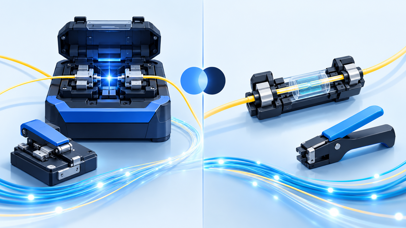
A B2B buyer's guide to choosing between fusion splicing and mechanical splicing: how each works, loss and cost comparisons, where each method fits, hybrid pigtail architectures and a procurement checklist.
Every fiber optic link, no matter how long or how short, ends at a splice or a connector, and the method you choose to join fiber to fiber decides how that link will behave for the next twenty years. For project buyers, network integrators and telecom contractors, the decision usually comes down to two technologies: fusion splicing, where an electric arc welds two prepared fiber ends into a continuous piece of glass, and mechanical splicing, where two cleaved fiber ends are held in precise alignment inside a mechanical assembly filled with index-matching gel. Both methods produce a working joint. Both are used every day on real networks. But they differ sharply in equipment cost, per-joint cost, loss performance, skill requirements, rework behavior and long-term reliability — and choosing the wrong one for a given project either inflates the budget or compromises the loss budget.
This guide is written for the person who signs the purchase order. It explains how each method actually works, what each one costs in practice, how their loss and reliability figures compare, and which project conditions favor which method. It closes with a procurement checklist you can use when you request quotations, so that the termination method specified in your tender matches the equipment, skills and maintenance model you actually have.
Why the Termination Method Is a Procurement Decision, Not Just a Technical One
On paper, splicing looks like a field engineering detail — something the installation crew handles after the cable is pulled. In practice, the termination method drives four cost lines that appear in your project budget long before the first fiber is fused:
- Capital equipment. A fusion splicer, a fiber cleaver, splice protection sleeves and an OTDR or light source and power meter form a kit that costs several thousand dollars before the first joint is made. Mechanical splicing requires only a cleaver and the splice assemblies themselves, which cost a few dollars each.
- Per-joint consumable cost. A fusion splice protection sleeve costs cents; the amortized cost of the splicer per joint falls as joint count rises. A mechanical splice assembly costs a few dollars every single time, whether you make ten joints or ten thousand.
- Labour skill and time. Fusion splicing is fast once the operator is trained — a joint in well under a minute of machine time — but the training, the machine calibration and the cleanliness discipline are non-trivial. Mechanical splicing takes slightly longer per joint but needs far less training.
- Rework and maintenance model. A fusion splice is permanent; remaking it means cutting the fiber back and splicing again, which consumes cable slack. A mechanical splice can often be reopened, cleaned and reassembled on site without cutting the fiber — valuable in locations where slack storage is limited or where the joint may need to be re-accessed.
Because these four lines scale differently with joint count, the "better" method depends on volume. A 144-core backbone cable entering a single splice closure produces a large block of joints where fusion wins decisively on cost and performance. A small campus retrofit with a dozen joints, no splicing equipment on site and no trained operator may be completed faster and cheaper with mechanical splices. The rest of this article gives you the numbers and the conditions behind that choice.
What Fusion Splicing Actually Is
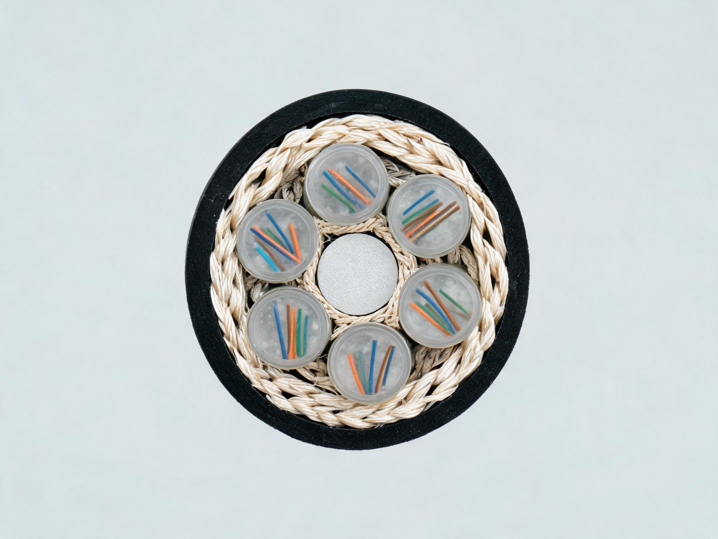
Fusion splicing joins two optical fibers by melting their prepared ends together with a controlled electric arc, producing a joint with essentially no physical gap and a continuous glass path. The sequence is standardized across machines and worth understanding, because every step influences the final loss:
- Strip. The fiber's outer jacket, strength yarn and 250 µm buffer are stripped back to expose the 125 µm glass cladding. Stripping tools must be kept clean; a nicked cladding at this stage becomes a future break.
- Clean. The bare glass is wiped with lint-free wipes and isopropyl alcohol. Residual gel or dust on the cladding causes the splicer's alignment cameras to misjudge the core position and inflates estimated loss.
- Cleave. The fiber is cleaved to produce an end face perpendicular to the fiber axis, typically within about one degree on a quality cleaver. Cleave angle is the single largest controllable contributor to fusion splice loss: a poor cleave shows up immediately in the splicer's estimated loss reading.
- Load and align. Both fibers are loaded into the splicer's holders. The machine aligns the cores, either by profiling the cladding surfaces (fixed V-groove or profile alignment systems) or by core-to-core alignment using imaging through the fiber, which achieves tighter results on fibers with different geometries.
- Fuse. The arc fires, melting the two ends and fusing them with controlled overlap. Modern splicers adjust arc power and duration for fiber type and ambient conditions.
- Protect. The bare splice is moved into a heat-shrink splice protection sleeve, which is shrunk onto the joint to restore mechanical strength before the fiber is coiled into the splice tray.
The result is a joint that is optically almost invisible. Fusion splices made with a calibrated machine and a clean cleave typically measure around 0.05 dB, and well-executed joints routinely fall at or below about 0.1 dB; these are typical industry values, and the acceptance figure for your own project should be confirmed against the specification sheet issued with the order and the test method in your contract. Reflectance of a fusion splice is extremely low because there is no physical interface between glass surfaces — there is no Fresnel reflection, which is why fusion is preferred on long-haul routes, CATV overlays and any link where return loss matters.
The Equipment Behind a Fusion Program
A fusion splicing capability is a kit, not just a machine. The core items are the fusion splicer itself, a precision fiber cleaver, stripping tools, alcohol and lint-free wipes, splice protection sleeves, and a work surface or shelter that keeps dust and wind off the splice area. For verification you need either an OTDR or a light source and power meter; an OTDR gives you the loss of each splice along a route and is the standard acceptance tool on outdoor builds. Machines also need periodic calibration, and electrodes need replacement after a defined number of arcs — typically a few thousand — so a serious splicing program budgets for consumable maintenance, not just the initial purchase.
That kit is exactly why fusion splicing is an economy of scale. Once the capital is spent and the team is trained, the marginal cost of one more splice is dominated by a protection sleeve worth a few cents and a minute of labour. Contractors who splice daily spread the equipment cost across thousands of joints and obtain the best loss performance available in the field.
Where Fusion Splices Live on a Real Network
Fusion splices concentrate at predictable points: the splice closures where an outdoor cable transitions or branches, the floor where a building entrance cable is split into pigtails for an ODF, and the transition from loose-tube outdoor cable to indoor tight-buffered cable. In the typical entrance facility, each fiber of the outdoor cable is spliced to a fiber optic pigtail, whose factory-terminated connector then lands in the patch panel. This hybrid — factory connector plus one field fusion splice per fiber — is the dominant architecture in modern ODF builds, and it is examined in detail later in this article. For a full treatment of how those joints and their slack are housed, see our guide to choosing a fiber optic splice closure and managing slack storage.
What Mechanical Splicing Actually Is
Mechanical splicing aligns two cleaved fiber ends inside a precision-molded assembly — a body with a V-groove or capillary channel, lids or clamps that press the fibers into alignment, and a chamber filled with index-matching gel. The gel bridges the microscopic gap between the two glass ends, suppressing the Fresnel reflection that a bare air gap would cause. The fibers are not melted or permanently joined; they are held in optical contact by the assembly. The field sequence is shorter than fusion's:
- Strip and clean the fiber exactly as for fusion — the same hygiene discipline applies, because contamination inside a mechanical splice is trapped permanently in the gel.
- Cleave the fiber. Cleave quality matters just as much as in fusion; a chipped or angled end face inside a mechanical splice produces elevated loss that no adjustment can recover.
- Insert the first fiber until it seats, then the second, so the two cleaved ends meet in the gel chamber.
- Close the assembly — flip the lids or actuate the clamp — and the splice is complete. There is no arc, no curing time in the most common designs, and no heat-shrink sleeve.
Mechanical splices are also produced in a form that doubles as a connector: field-installable connectors, which crimp or clamp a pre-polished fiber stub to a cleaved field fiber. These products have made mechanical termination the default for FTTH drop cables and small indoor jobs where a splicer would never pay for itself.
Loss performance is solid but not in fusion's class. A quality mechanical splice typically measures in the range of about 0.1 to 0.5 dB, with 0.2 dB to 0.3 dB a realistic planning average for field work; these are typical industry values and the exact specification belongs on the datasheet of the product you buy. Return loss is lower than a fusion splice because two glass surfaces meet through gel rather than being one continuous piece of glass — reflective performance is typically in the -35 dB to -50 dB range depending on the design, which is acceptable for most access and enterprise links but is a real constraint on high-rate digital links and CATV overlays where reflections degrade signal quality.
The Appeal: No Machine, No Program, No Waiting
The commercial argument for mechanical splicing is simplicity. There is no capital equipment beyond a cleaver and hand tools, no electrode replacement, no calibration, and no multi-day operator course. A technician who can strip, clean and cleave fiber — the same skills needed for connector work — can produce a working splice in a few minutes. For service interruptions, a mechanical splice is often the fastest repair available: re-strip, re-cleave, insert, done. Many outside-plant crews carry a handful of mechanical splices purely as an emergency restoration item precisely because they need no power and no equipment.
Reusability is the second advantage. Because the fibers are clamped rather than welded, most mechanical splice designs can be opened, the fibers cleaned and re-inserted, and the splice remade — provided the gel chamber is refreshed or the assembly is a type designed for reopening. On short indoor runs where slack storage is minimal, the ability to remake a joint without cutting fiber back is a genuine operational benefit. The limits show up in the numbers: each remade joint has consumed some of the gel's effectiveness, and a mechanical splice is a larger, stiffer body than a protected fusion splice, which matters inside a densely packed splice tray.
Fusion vs Mechanical: The Head-to-Head Comparison
The table below collects the planning numbers in one place. All loss figures are typical industry values for guidance; the figures that govern your acceptance test must come from the datasheets of the specific splice assemblies, pigtails and equipment you purchase, stated as "subject to the specification sheet."
| Criterion | Fusion Splicing | Mechanical Splicing |
|---|---|---|
| Typical insertion loss | ~0.05 dB; routinely ≤0.1 dB | ~0.1–0.5 dB; 0.2–0.3 dB planning average |
| Typical reflectance | Extremely low (no glass–glass interface) | Roughly -35 to -50 dB depending on design |
| Capital equipment | Splicer, cleaver, tools, verification kit: several thousand USD | Cleaver and hand tools only |
| Per-joint consumable | Protection sleeve, cents | Splice assembly, a few USD each |
| Time per joint (trained tech) | Roughly 1–2 minutes including sleeve | Roughly 2–5 minutes depending on design |
| Skill requirement | Training plus daily practice | Minimal; connector-level skills suffice |
| Joint count economy | Improves with volume | Flat — cost per joint is constant |
| Rework model | Cut back and re-splice; consumes slack | Often reopenable and remade on site |
| Long-term reliability | Excellent; permanent glass joint | Good; depends on gel aging and strain relief |
| Best fit | Backbone, outdoor, high fiber count, new builds | Small jobs, FTTH drops, emergency restoration |
Read vertically, the table explains each method's economics; read horizontally, it explains why hybrid architectures exist. No single column wins every row, and real projects almost always mix both methods — fusion where fiber counts concentrate, mechanical where joints are isolated and rare.
The Cost Crossover: When Each Method Pays for Itself
The fastest way to choose between the methods on a given project is to find the crossover point between capital investment and per-joint cost. Model it with round numbers — the point is the structure of the decision, not the exact dollars, which vary by brand, region and procurement terms.
Suppose a fusion kit — splicer, cleaver, consumables and verification gear — costs around USD 10,000, and each fusion joint consumes a sleeve plus two or three minutes of trained labour. Suppose a mechanical splice assembly costs around USD 3 to 5 per joint with negligible equipment cost. At 50 joints, the fusion route has spent the whole kit and produced joints costing hundreds of dollars each in amortized terms; mechanical wins on cost and gets the job done. At 2,000 joints, the kit is amortized to a few dollars per joint and still falling, the joints are faster to make, and their loss is lower — fusion wins on cost and performance, and the margin widens with every additional joint.
Three refinements make this model more realistic. First, equipment is rarely dedicated to one project: a contractor's splicer is amortized across its whole year of work, which moves the crossover point dramatically downward — often to jobs of a few dozen joints if the kit already exists. Second, labour cost differs by market; in high-wage regions the faster fusion process offsets kit cost sooner. Third, rework costs are asymmetric: a failed mechanical splice is usually reopened for free, while a failed fusion splice consumes slack, but fusion's failure rate on a calibrated machine is very low in the first place. The honest comparison therefore asks not only "how many joints?" but "whose equipment, whose labour, and what happens when a joint must be remade?"
For buyers procuring splicing services from an installer rather than owning the equipment, the crossover becomes a line item in the quotation: per-joint pricing on large fiber counts should fall well below small-job rates, and a quotation that prices 144 fusion splices at the same per-joint rate as 12 deserves a question.
Performance, Reliability and the Long-Term View
Loss at installation is only half the story; the other half is how the joint behaves after five, ten or twenty years in the field. Here the two methods differ in mechanism rather than in a simple ranking.
A fusion splice is a single continuous piece of glass. Once protected by its sleeve and seated in a splice tray, it has no moving parts, no gel to age and no interface to creep. Its documented failure modes are almost entirely mechanical — a fiber stressed by poor slack storage, a tray crushed during a later visit, or rodent damage to the cable that reaches the splice point. When the joint itself is made well, fusion's long-term statistics are effectively those of the fiber itself.
A mechanical splice relies on three physical elements remaining stable: the alignment geometry, the clamping force and the index-matching gel. Quality assemblies are engineered for decades of service, and their long-term performance in temperate indoor environments is well proven. The watch items are environmental: prolonged high temperature or freeze-thaw cycling can affect gel properties over many years, and any assembly whose strain relief is under-specified can transmit load to the fiber. This is why datasheet age-life and temperature-range figures deserve genuine attention during procurement, and why mechanical splices outdoors should be specified with an operating temperature range matched to the route — a point to confirm "subject to the specification sheet" for the product actually quoted.
There is also a testing asymmetry worth knowing before acceptance. A fusion splicer reports an estimated loss for every joint it makes, and the OTDR then verifies those joints independently along the whole route — a clean two-source record that most project owners require on outdoor builds. Mechanical splices also appear on an OTDR trace, but a bilateral measurement is more important for them because their reflectance is higher; a joint that looks acceptable from one end can hide a reflective artifact measurable from the other. Our guide to using an OTDR to accept a new fiber installation covers the measurement practice in detail.
When Fusion Splicing Is the Right Choice
The case for fusion is strongest when several of the following conditions hold at once:
- High fiber counts concentrate in one place. A 96- or 144-core outdoor cable entering a building or a closure generates enough joints to amortize any splicing kit within the project itself.
- The route is long and the loss budget is tight. Every 0.2 dB saved per joint compounds across dozens of joints in series; on a metro segment with 48 joints, the difference between 0.05 dB and 0.3 dB per joint is more than 10 dB — an entire link margin. Long runs of outdoor G.652D single mode cable are planned around exactly these budgets.
- Return loss matters. High-speed digital links, DWDM routes and CATV overlays are all sensitive to reflections; a joint with no glass-glass interface is the clean answer.
- There is an ongoing splicing program. Contractors, ISPs and utilities that splice weekly are the natural owners of fusion equipment; the kit pays for itself as a tool, not a project expense.
- The specification demands it. Many tenders for backbone and carrier work simply specify fusion splicing, and the specification is the buyer's protection here: it guarantees the lowest-loss joint available and an OTDR-verifiable record for every fiber.
When Mechanical Splicing Makes Sense
Mechanical splicing earns its place under almost opposite conditions:
- Few joints, one-time job. A campus retrofit, a small building entrance or a repair branch with a dozen or two joints cannot justify mobilizing a splicing program, and the per-assembly premium is trivial against the total project value.
- No trained operator and no time to create one. When the field crew already terminates connectors confidently, mechanical splices keep the whole job within their existing skill set.
- FTTH and last-meter terminations. Field-installable connectors on drop cable are a mechanical-splice product by design; millions of homes are connected this way every year because a splicer at every subscriber premises is economically absurd.
- Emergency restoration. Restoring a cut cable with mechanical splices overnight and remaking the joints properly with fusion during a planned window is standard outside-plant practice — speed first, permanence later.
- Tight slack and possible re-access. In enclosures where fiber slack is scarce, a reopenable joint avoids cutting fiber back on every rework.
The Hybrid Architecture Most Networks Actually Use
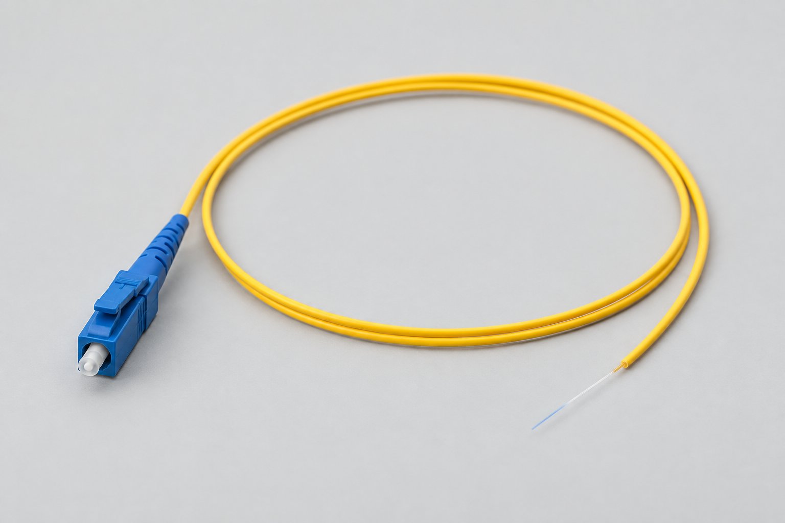
Step back from the binary comparison and look at how real entrance facilities are built: they combine both philosophies by placing each method where it is strongest. The outdoor cable arrives with loose-tube, gel-filled construction. Inside the entrance closure or ODF, each fiber is fusion-spliced to a pigtail — one short joint, made by the crew's splicer, in a block of joints where fusion is at its most economical. The pigtail's connector, however, is not made in the field: it is factory-terminated, polished and tested before shipping.
This division of labour is deliberate and worth understanding as a buyer, because it maps precisely onto the strengths of factory and field work. Connector termination is the least repeatable field operation — it depends on cleave angle, epoxy cure, polish quality and ferrule handling in a live rack. Fusion splicing, by contrast, is the most repeatable field operation, with a machine-measured result for every joint. Moving the connector into the factory and leaving the splice in the field gives each fiber exactly one field operation, and it is the operation the crew does best.
The numbers make the argument concrete. On a factory-terminated pigtail, insertion loss is typically specified at ≤0.3 dB with a ≤0.5 dB maximum, and return loss at ≥50 dB for UPC end faces and ≥60 dB for APC end faces, measured on the finished assembly; combined with a fusion splice at roughly 0.05 dB typical, the total fiber path from cable to panel port sits comfortably inside the 0.75 dB to 1.0 dB allowance most link budgets assign to the termination. All figures are typical values — the binding numbers are those on the specification sheet supplied with the order. The factory-polished end face also behaves differently from a field-polished one at acceptance: it arrives with its test record, and the measured value at acceptance should match that record rather than depend on which technician built the port that day.
Specifying the pigtail correctly is therefore part of the splicing decision. Match the connector family to the panel (SC, LC or FC), the fiber grade to the cable being spliced (G.652D single mode or OM3/OM4 multimode), and the end face to the rest of the link — mixing UPC and APC in one path is a classic cause of elevated return loss. Our guide to reading patch cord specs: insertion loss, return loss and polish types explains how these figures are stated on datasheets, and how adapters and mating hardware complete the path, as covered in our patch cord and adapter buyer's guide.
A Procurement Checklist for Termination Methods
Whether you buy termination as a service from an installer or as components from a manufacturer, the questions below turn the analysis above into a checklist you can send with your RFQ:
- State the joint count and layout explicitly. Fiber counts per cable, number of closures, number of building entrances, and which joints are permanent versus likely to be re-accessed. Volume decides the economics.
- Require loss figures with their basis. Ask for typical and maximum insertion loss per joint type, the reflectance specification, and the test method (splicer estimate, OTDR bilateral, insertion-loss measurement). Accept only figures stated as "subject to the specification sheet" with the actual product documents attached.
- Specify the acceptance method. For fusion programs, OTDR traces per fiber with a defined pass threshold are the norm. For mechanical splices, require bilateral measurement where reflectance matters.
- Confirm equipment and consumable ownership. If the installer brings a splicer, is mobilization charged per project or amortized per joint? If you buy mechanical assemblies, confirm the operating temperature range and whether the design is reopenable.
- Plan the protection and storage. Every splice — fused or mechanical — needs a sleeve or strain-relieved seat and slack storage; the closure and tray plan is part of the same purchase. Our splice closure guide linked above covers the sizing logic.
- For pigtails and factory terminations, ask for the test record. Factory-terminated ends should ship with measured insertion and return loss. Confirm connector family, fiber grade, end face and jacket per configuration, and the warranty basis — all Nexora fiber optic products carry a 12-month warranty from shipment date.
For a structured starting point on what else belongs in a quotation request, see our guide to the information to include in a fiber optic cable RFQ.
Two Worked Scenarios: Applying the Decision Framework
Abstract criteria become clearer on concrete routes, so here are two projects of the kind our customers run, worked through the framework above.
Scenario A: A 72-Core Metro Backbone Segment
A carrier is extending a metro ring: 9 km of outdoor cable, three splice closures along the route, and a building entrance terminating into an ODF with 72 ports. Joint count is roughly 144 in the closures plus 72 pigtails at the entrance — over 200 joints on one project. The loss budget allows about 25 dB for the span, of which fiber attenuation at 1310 nm consumes roughly 3.2 dB across 9 km (at the ≤0.36 dB/km typical figure for G.652D cable, subject to the specification sheet), leaving generous room for joints but also room for DWDM reflectance sensitivity. The installer runs fusion splicing every week. The decision is unambiguous: fusion throughout, OTDR acceptance per fiber, mechanical splices carried in the restoration kit only. The 72 pigtails at the entrance are factory-terminated SC/UPC, each fiber receiving exactly one field fusion splice. In this scenario, specifying mechanical splices to "save equipment cost" would add tens of dB of cumulative loss headroom risk and would fail the carrier's acceptance specification anyway.
Scenario B: A Campus Retrofit with 18 Joints
A university is connecting five buildings with indoor riser cable and short outdoor runs between ducts. The integrator quotes the job including termination. Total joints: about 18, spread across six locations, each location holding two to four joints. No one on the crew operates a splicer daily; the nearest trained operator is contracted by the day. Here the crossover analysis favors a mixed answer: use mechanical splice assemblies at the small distributed points — each costs a few dollars against a splicing mobilization measured in hundreds — and reserve one contracted fusion day for the building entrance where 12 fibers land in the ODF and become pigtails. Total optical performance still meets a 0.75 dB-per-termination allowance comfortably, and the campus facilities team, which will maintain the network with two technicians and a toolbox, inherits a network they can service without calling a specialist for every repair.
The pattern generalizes: joint density and the maintenance organization that will inherit the network decide the split, not brand loyalty to either technology.
Common Procurement Mistakes Around Splicing
Across quotations we review, the same handful of errors appears repeatedly. Each one is avoidable at the RFQ stage:
- Specifying the method without the joint count. A tender that says "fusion splicing" for a 10-joint retrofit pays fusion mobilization for no performance benefit; a tender that leaves the method open on a 200-joint backbone invites the installer to choose the cheapest path, which is rarely the lowest-loss one. State the count and let it drive the method.
- Comparing datasheet losses across different test methods. A splice quoted "0.1 dB (splicer estimate)" is not the same claim as "0.3 dB (OTDR bilateral)". When comparing suppliers, normalize the measurement method first.
- Forgetting the sleeve and tray in the budget. Splice protection sleeves, tray space and slack length are small line items that become schedule problems when omitted. If closures are undersized for the joint count, the splices themselves suffer.
- Ordering pigtails without the configuration matrix. Connector family, fiber grade, end face and jacket length must be listed per group. A shipment of SC/UPC pigtails arriving for an APC panel is a two-week delay hidden inside one missing line of the purchase order.
- Treating warranty and workmanship as the same thing. The manufacturer's 12-month warranty from shipment covers defects in the components; the installer's workmanship warranty covers the joints. Networks that document both at handover resolve fault responsibility in days instead of months.
Maintenance and Rework in the Years After Handover
The termination method chosen at construction keeps paying dividends — or charging fees — for the whole life of the network, so it is worth planning maintenance behavior at purchase time.
Networks built on fusion splicing maintain well through the OTDR: an annual or event-triggered trace re-measures every joint in the route and locates degradation to within meters, so the crew arrives at the correct closure with the correct closure key and slack plan. Remaking a fusion splice requires slack in the tray — one more reason our closure guide emphasizes generous slack storage. Budget one splice remake per closure visit as a planning allowance, and the maintenance schedule becomes predictable.
Networks built with mechanical splices maintain well through spares: a box of assemblies in the facilities cupboard converts most joint faults into a same-day fix by the in-house team. The discipline to keep is cleanliness — the gel chamber is unforgiving of dust — and the habit of replacing rather than reusing an assembly whose loss has crept upward. On networks where both methods coexist, the restoration kit holds mechanical assemblies for speed, and the planned-work calendar holds the splicer for permanence, exactly as in the restoration playbook above.
Finally, keep the as-built records alive. The acceptance OTDR traces, the factory test records for every pigtail and patch cord, and the closure layout diagrams are the documents that make year-five maintenance a routine instead of an archaeology project. Suppliers who ship measured, documented components — and an RFQ that asks for those records up front — are contributing to that maintenance model before the first splice is ever made.
Frequently Asked Questions
Is a fusion splice always better than a mechanical splice?
On pure optical performance, yes — lower loss and far lower reflectance. But "better" in procurement means fit for the project: on a 15-joint indoor retrofit with no splicing equipment on site, a mechanical splice is faster, cheaper and entirely fit for purpose. Fusion wins where fiber counts are high, budgets are tight in dB, and a splicing program already exists.
How long does each type of splice take?
A trained technician completes a fusion splice, including protection sleeving, in roughly one to two minutes of working time. A mechanical splice takes roughly two to five minutes depending on the assembly design. Machine time and curing time differ, so compare end-to-end times on your own crews rather than datasheet claims.
Can a mechanical splice be reused?
Many designs can be opened, cleaned and reassembled, which is one of their procurement advantages where slack storage is limited. Gel condition degrades with each remaking, so treat reuse as a maintenance allowance rather than an unlimited feature, and confirm reopenability on the specific product's datasheet.
Do mechanical splices meet carrier acceptance standards?
It depends on the tender. Carrier backbone specifications almost always require fusion splicing with OTDR records per fiber. Access-level and enterprise work commonly accepts mechanical splices within stated loss limits. The acceptance standard is a contract document, so confirm the threshold and the measurement method before ordering rather than after installation.
Why do so many ODF builds use pigtails instead of field-polished connectors?
Because the pigtail removes the least repeatable field operation — connector termination — and replaces it with the most repeatable one — fusion splicing. The factory-terminated end arrives polished and tested to ≤0.3 dB typical insertion loss with UPC ≥50 dB / APC ≥60 dB return loss (typical values, subject to the specification sheet), and the acceptance test compares against a factory record rather than field conditions.
What training does fusion splicing require?
Beyond an operator course on the specific machine, the real requirement is disciplined daily practice: clean stripping, consistent cleaves, arc calibration for local conditions, and careful tray dressing. Crews that splice occasionally tend to produce more variable results than the machine is capable of, which is one more reason isolated joints often suit mechanical products better.
How does warranty apply to splicing-related products?
For factory-made components such as pigtails, patch cords and adapters, the manufacturer's warranty covers manufacturing defects. All Nexora fiber optic products carry a 12-month warranty from the shipment date. Field workmanship — the splice itself — falls under the installer's workmanship warranty, which is a separate agreement and worth stating explicitly in installation contracts.
Where does each method sit in an emergency restoration plan?
Standard practice is mechanical splices for overnight restoration — no power, no equipment, fastest path to service — followed by fusion remakes during a planned maintenance window. Keeping a small stock of mechanical splice assemblies with the restoration kit is inexpensive insurance for any network with aerial or direct-buried exposure.
Working with Nexora on Termination Planning
Nexora Communications manufactures fiber optic cables, patch cords, pigtails and adapters in Shenzhen, supplying OEM/ODM programs and project buyers in more than 50 countries. Termination planning sits at the intersection of our product lines: the outdoor and indoor cables that carry fiber to the splice point, the factory-terminated pigtails that receive the fusion splice, and the patch cords and adapters that complete the path from the panel to the equipment.
Because every configuration is different, we quote per project: tell us the fiber counts, deployment method, connector families and end faces, and we will confirm the matching cable construction, pigtail configurations and packing for your splicing plan. Performance figures in this article are typical industry values stated for planning guidance; the specification sheet issued with your order is the binding document for every parameter, and all products are covered by a 12-month warranty from shipment date. When you are ready to align cable, pigtails and termination hardware for your next build, our team is one quotation request away.
Planning a fiber build and need cable and termination components that arrive tested and documented? Share your route details and fiber counts with us, and we will return a configuration proposal with the full specification sheets attached.