
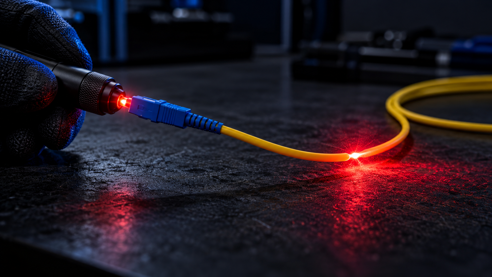
A practical field guide to troubleshooting fiber optic links with a visual fault locator: when to reach for the VFL, how to read fault glow signatures, and how to build VFL checks into acceptance and maintenance routines.
When a fiber optic link suddenly goes dark, every minute of downtime has a price attached. Network operators, ISPs, and enterprise IT teams all face the same pressure: find the fault, confirm the cause, and restore the link before users notice. Among the handful of tools that live in a fiber technician's pouch, the visual fault locator (VFL) is the cheapest, fastest, and most misunderstood. This guide explains, from a manufacturer's field perspective, how to use a visual fault locator to troubleshoot a fiber optic link step by step, how to read the light signatures it produces, and how to build VFL checks into your acceptance and maintenance routines so that faults are caught before they become outages.
The advice in this article is written for B2B buyers and technical teams who specify, purchase, and maintain fiber optic cable, patch cords, adapters, and pigtails. Where we quote numbers such as output power or insertion loss, they are typical industry values for orientation only — always confirm against the product datasheet before making a purchasing or acceptance decision.
What a Visual Fault Locator Is — and What It Is Not
A visual fault locator is a small handheld light source, usually pen-shaped, that injects bright visible red light — typically at a nominal 650 nm wavelength — into one end of a fiber. Visible red light behaves differently from the 1310 nm or 1550 nm light your network transmitters use. Because its wavelength is short and its photons are energetic in the visible spectrum, red light escapes readily wherever the glass is bent too tightly, cracked, contaminated with a severe break, or joined by a poor fusion or mechanical splice. That escaping light is the entire diagnostic principle: you inject red light at one end and look for glowing spots along the jacket or at connector interfaces.
Most field-grade VFLs use a Class 2 laser diode limited to 1 mW or less of coupled output power, which is enough to reveal faults through standard 0.9 mm, 2.0 mm, or 3.0 mm buffer coatings over practical working distances, commonly quoted by manufacturers in the range of 3 to 5 km for jacketed cable, though the useful detection distance depends heavily on cable construction and ambient light. Treat those figures as typical values and confirm the specific product's datasheet. Higher-power units exist, but more milliwatts do not automatically mean better troubleshooting, because excessive power can wash out the subtle glow signatures that distinguish a tight bend from a hard break.
It is equally important to be clear about what a VFL is not. It is not a power meter, so it will not tell you the insertion loss of a link in decibels. It is not an OTDR, so it will not give you a trace, a distance-to-fault reading, or a splice-by-splice loss profile. And it is not a substitute for an end-face inspection microscope. A VFL answers one deceptively simple question with remarkable speed: is there a gross physical defect somewhere along this fiber that visible light can reveal? When the answer is yes, it often shows you exactly where.
When a VFL Should Be Your First Test — and When It Should Not
The VFL earns its place as the first tool out of the bag in several recurring situations. First, when a single patch cord is suspected: before swapping cords at random, thirty seconds with a VFL confirms whether the cord conducts light cleanly or shows a visible break or bend defect. Second, when a link that worked yesterday is dead today after physical disturbance — a cabinet was moved, a tray was re-routed, a door crushed a slack loop. Gross mechanical faults are precisely what visible light finds fastest. Third, during termination work: a newly polished connector or a fresh fusion splice can be smoke-tested with red light before the assembly is packed or installed, catching cracks and misaligned splices at the bench where rework is cheap.
Fourth, when you need to identify which of many ports or fibers corresponds to which label. A VFL doubles as a fiber identifier in a pinch: inject red light at the far end and watch which port glows at the patch panel. Fifth, in FTTH and campus networks where drop cables run through tight wall entries and shallow raceways, the classic macrobend leak shows up as a bright spot exactly where the cable was forced around a corner — an immediate, location-specific answer that no other handheld tool provides as quickly.
There are equally clear cases where the VFL should not lead. If a link shows high loss but still passes light, the cause may be dirty or damaged connector end faces — a problem that is often invisible to a VFL through the connector body and far better diagnosed with inspection and cleaning, as covered in our guide to cleaning and inspecting fiber optic connectors. If the link is long, buried, or aerial with faults spread over kilometers, an OTDR is the right instrument because it localizes faults by distance; our article on using an OTDR to accept a new installation walks through that workflow. And if the fault is in a live DWDM system, you must coordinate with operations before disconnecting anything: a VFL test requires the fiber to be dark at the test end.
A practical triage rule used by many field teams: check power at the receiver, inspect and clean both connector end faces, re-test with a power meter, and only then bring out the VFL to hunt for physical defects — or bring out the OTDR if the run is too long to inspect visually. This ordering prevents the most common wasted effort: hunting for a break that is actually a fingerprint on a ferrule.
VFL and OTDR: Which Fault-Finding Tool to Reach for First
Because both instruments localize faults, buyers sometimes ask which one to standardize on. The honest answer is that they solve different halves of the problem, and mature maintenance programs carry both. The table below compares them on the dimensions that matter during a real outage.
| Dimension | Visual Fault Locator | OTDR |
|---|---|---|
| Primary question answered | Where is the gross defect that visible light can escape from? | What is the loss profile along the fiber, and at what distance? |
| Time to a usable result | Seconds to a few minutes | Minutes, plus trace interpretation |
| Distance capability | Typically up to about 3–5 km on jacketed cable, datasheet-dependent | Kilometers to tens of kilometers depending on module |
| Quantitative loss reading | No | Yes, per event and per span |
| Detects dirty end faces | Unreliable — use inspection scope | Indirectly, as a reflective event |
| Shows fault through cable jacket | Yes, as a visible glow at the defect | No, only as a distance marker |
| Typical cost tier | Low — pocket tool for every technician | High — shared or specialist instrument |
The workflow that gets the best of both: when a fault is reported, use the VFL first on the accessible portions — patch cords, panel-to-panel jumpers, visible drop sections — because a thirty-second check frequently ends the investigation. If the VFL shows nothing and the link still fails, the OTDR takes over to localize the fault by distance, and the VFL then confirms the repair on the ground once the crew reaches the physical spot. Teams that skip the VFL step often dispatch an OTDR crew to a site, only to find a crushed patch cord behind a cabinet that a red pen would have exposed in half a minute.
Key VFL Specifications Buyers and Field Teams Should Check
Because VFLs are inexpensive, purchasing decisions are often made carelessly — and a poor-quality unit wastes more time in the field than it costs. When evaluating VFLs for a tooling standard or a project kit list, check the following specifications against the datasheet rather than the marketing copy.
- Emitter type and wavelength. Most units use a 650 nm laser diode; some use an LED. A laser diode concentrates enough power in the fiber's core to travel useful distances and produce crisp leak signatures, while an LED-based pen only works over short cords. For installation work, specify a laser-diode VFL at a nominal 650 nm — typical values; confirm the exact emitter and wavelength on the datasheet.
- Output power class. Field units are typically Class 2 laser products with coupled power at or below 1 mW into single mode fiber. This is the sweet spot: bright enough to show leaks through 0.9 mm–3.0 mm buffers, yet safe under normal handling discipline. Higher-power Class 3R units extend detection distance but raise safety obligations.
- Connector interface. A universal 2.5 mm adapter accepts FC, SC, and ST plugs; a flip-out or interchangeable 1.25 mm adapter covers LC and MU. If your plant and customer base are LC-heavy — as most data center and FTTH projects are today — make sure LC operation is native, not an afterthought. A VFL that cannot mate directly with the connectors you actually use forces improvised adapters that introduce their own loss and wobble.
- Continuous and pulse modes. A continuous mode gives the brightest, easiest-to-see glow; a pulsed mode (commonly a 1–2 Hz blink) helps the eye distinguish the VFL's light from other red sources and conserves battery. Both modes are useful; pulse mode is nearly essential in bright machine halls where steady red light is hard to localize.
- Battery and runtime. Typical units run on two AAA cells for tens of hours of intermittent use. Check the datasheet's runtime figure and, for fleets, prefer a common battery format so crews never idle waiting for a charger.
- Mechanical durability. Pocket tools live with keys and pliers. A metal housing, a capped output port, and a belt clip are not luxuries — they determine whether the unit survives its first month.
One more buying note belongs here. The VFL itself is the tool, but the accuracy of every VFL test depends on the quality of the consumables it touches: patch cords with well-polished end faces, adapters with aligned ceramic split sleeves, and pigtails with clean splices. Cheap cords with high, unstable insertion loss generate exactly the intermittent behavior that sends crews chasing phantom faults. Sourcing cords and adapters from a manufacturer who tests every assembly — and backs them with a warranty of 12 months from shipment date — is part of the troubleshooting strategy, not just a purchasing line item.
Laser Safety: Working with Visible Red Light the Right Way
Visible red laser light has a hidden advantage and a hidden trap. The advantage: your eye's blink reflex and aversion response respond to bright visible light, which makes Class 2 VFLs forgiving of brief accidental exposure. The trap: because the beam is visible, people treat it casually — and casual habits around any laser in a fiber environment are how accidents happen, especially because fiber light is invisible in the bands that actually carry network traffic.
Follow these rules on every VFL job:
- Never look directly into the output port of a VFL or into the ferrule of a fiber you suspect is carrying VFL light. Inspect leaks and glowing connectors indirectly, or use a viewing filter or camera-based scope when checking an end face.
- Treat every fiber as live until proven otherwise. In a shared splice enclosure or ODF, another wavelength may be carrying traffic even when your end is dark. Coordinate and, where required, tag out before disconnecting.
- Do not use a VFL to shine across a room as a pointer. Red fiber light scatters visibly, and direct exposure at close range is unpleasant and unprofessional.
- Cap the VFL when it is in your pocket. An uncapped unit in a pocket can pressure-activate and bathe the inside of a tool bag in laser light — and worse, drain its batteries before the next callout.
- Never view a suspected high-power transmission fiber with optical instruments unless they are rated for it. A VFL session is also a good moment to reinforce that habit for 1310/1550 nm traffic.
These rules cost nothing and keep the VFL the safest instrument in the bag. They should appear verbatim in your contractor onboarding materials.
Prepare the Link Before You Test: Clean, Disconnect, Isolate
VFL troubleshooting fails most often not because of the tool, but because the link was not prepared. Three preparation steps take two minutes and eliminate most false readings.
Step 1 — Clean both ends. Dust, finger oil, and dried residue on connector end faces scatter light before it even enters the fiber under test. Inspect and clean with one-click cleaners or lint-free wipes and optical-grade isopropyl alcohol, following the discipline in our connector cleaning guide. A dirty launch connector can make a healthy cord look dark and a healthy link look broken.
Step 2 — Disconnect what you must. A VFL test is performed on an isolated fiber. At a patch panel, unplug the cord from the adapter so you are not injecting light into a shared backplane or splicing onto a live span. In a splice enclosure, open the relevant tray only after confirming the fiber is dark at your end.
Step 3 — Isolate the segment. Decide exactly what you are testing: the patch cord alone, the cord plus the panel adapter, or the full link to the far end. Testing in segments is what turns a vague "link is down" into a located defect. If the cord tests clean but the full link fails, the fault is in the infrastructure — the backbone cable, a splice, or a panel adapter — and your segmenting has just halved the search area.
Step-by-Step: Testing a Patch Cord with a VFL
Patch cords are both the most replaceable and the most abused element in any network. Crushed by cabinet doors, kinked around cable managers, and mated thousands of times, they are the first thing a VFL should check. The procedure below takes under a minute per cord.
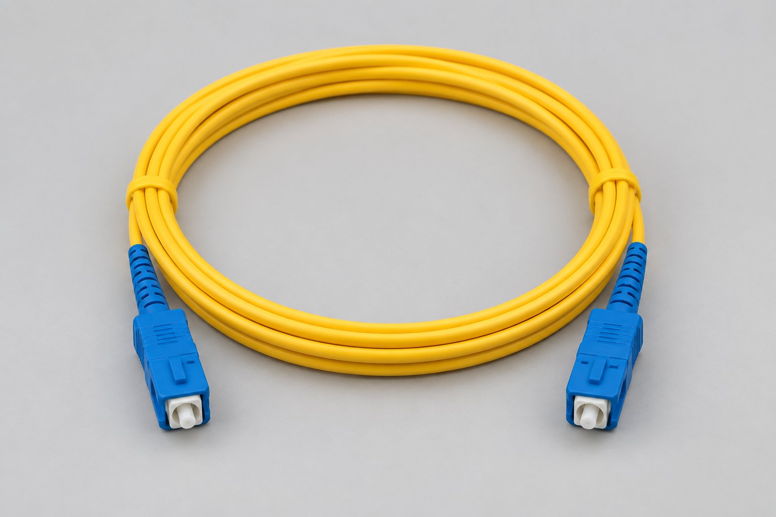
1. Clean and inspect both connectors. Wipe the ferrules, confirm the ceramic is intact, and check the polish zone under a scope if one is available. A chipped ferrule will not be fixed by any amount of red light.
2. Mate the cord to the VFL. Insert one end firmly into the VFL's adapter. On SC and FC plugs, feel the latch or bayonet seat fully; a half-seated connector leaks light at the launch and dims the entire test.
3. Activate continuous mode and observe the far end. The light emerging from the opposite connector should form a bright, steady red dot. Aim it at a palm or a light-colored surface a few centimeters away — never into anyone's eyes — and confirm the output is strong and even.
4. Sweep the cord slowly. With the light on, pass the entire length of the cord between your fingers, paying attention to any section that was coiled tightly, pinched, or stepped on. A healthy cord shows no glow at all through the jacket. A pinched or over-bent section shows as a localized bright spot; a complete break shows as a dramatic red flare close to the break point, with no light at the far end.
5. Flex-test suspicious points. If a faint glow appears, gently increase and decrease the bend radius at that point while watching. If the glow brightens as the bend tightens, the fiber is intact but stressed — the cord will pass light today and fail in service. Any cord that shows a repeatable glow at a fixed point should be scrapped or clearly quarantined, not re-issued to stock.
6. Check both directions if results seem odd. A marginal break can couple differently depending on launch geometry. Sixty seconds to reverse the cord and re-test removes doubt on borderline findings.
Quarantine discipline is what makes this routine valuable over time. Mark suspect cords, log the location and date, and replace them with tested stock. For high-turnover environments, keeping a supply of tested single mode cords such as the SC-SC single mode G.652D patch cord or the LC-LC duplex single mode patch cord means a quarantined cord never has to be pressed back into service.
Step-by-Step: Testing an Installed Link from One End
When the fault is somewhere in the fixed infrastructure — a backbone run, a riser, a campus duct route — the VFL is still your fastest first instrument, provided the link is short enough for its light to reach the defect and for escaping light to be noticed. The procedure changes slightly from cord testing because you no longer control the whole path in your hands.
1. Confirm the fiber is dark. At your test end, disconnect the customer equipment or patch cord and verify with a power meter that no traffic light is present on the fiber. Injecting VFL light into a live span is both a safety issue and a service risk.
2. Launch and listen to the far end. Mate the VFL to the launch connector, activate continuous mode, and have a colleague (or a phone camera) observe the far end of the link. Light arriving at the far end confirms the fiber is not fully severed — which means your fault is high loss, not open, and the VFL glow signature hunt begins.
3. Walk the route with the light running. Follow the cable path — trays, risers, wall entries, splice enclosure inlets — watching the jacket for any localized glow. In dim corridors and ceiling spaces this is dramatic: the defect literally lights up. In bright plant rooms, use the pulsed mode and shade the cable with your body or a dark cloth.
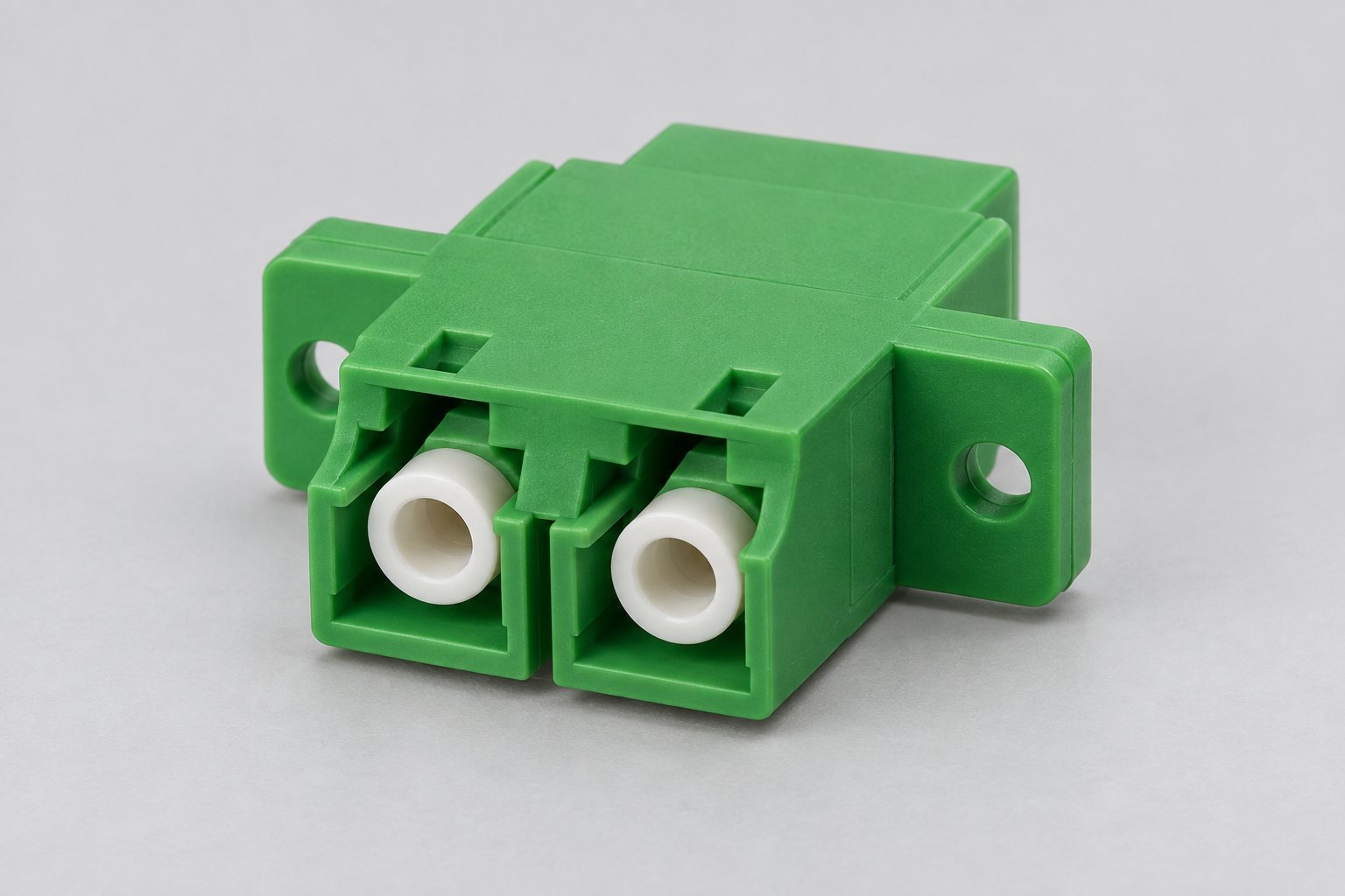
4. Interpret what you find at panels. Where the cable terminates on adapters, check whether light glows around the adapter body. A misthreaded or damaged split sleeve can misalign two ferrules enough to leak red light around the joint; the fiber itself may be perfect. Swapping the adapter is a two-minute fix that avoids an unnecessary splice crew dispatch. Keeping quality adapters in stock — for example the LC/APC duplex fiber optic adapter for high-return-loss APC links — turns that finding into a same-visit repair.
5. Record the segment verdict. Whether the VFL finds the fault or clears the accessible route, write down what was tested and what was found. If the VFL clears everything visible, the fault is inside a closed section — duct, buried run, or splice enclosure — and the OTDR takes over with a precise distance-to-fault reading.
Reading the Glow: What Different Fault Signatures Look Like
Experience turns the VFL from a break detector into a diagnosis tool. The pattern and brightness of escaping light tell a trained eye what kind of defect is present, and how urgent the repair is. The signatures below are the ones field teams encounter most.
- The tight-bend halo. A soft, diffuse red halo wrapped around the cable at a specific point, brightest at the inside of the curve, is the classic macrobend signature. The fiber is intact but bent below its minimum bend radius — common behind cabinets, at sharp wall entries, and in over-filled cable managers. The link may pass traffic now and fail later under temperature movement; the fix is to re-route with proper radius, typically at least ten times the cable diameter during handling for standard patch cord construction (typical value — confirm the specific cable's datasheet).
- The pinched-cable spot. A concentrated bright spot with a sharp edge usually means the buffer has been locally crushed — a cable tie over-tightened, a door edge, a clamp. The glass may be unbroken but micro-cracked. Treat it as a pending failure: the cord should be replaced, and the fixed cable scheduled for re-termination or protection.
- The hard-break flare. A dramatic, wide flare of red light with little or no light downstream is a complete or near-complete fracture — a cord yanked from a connector, a cable cut during other works, or a crushed outdoor drop. The location is usually visible to within a centimeter. This is the signature that makes the VFL famous.
- The connector-rim ring. A ring of red light around a connector boot or adapter body suggests launch leakage: the plug is not fully seated, the adapter sleeve is worn, or the ferrule end face is damaged. Unplug, inspect, clean, and re-seat; replace the adapter if the ring persists with a known-good cord.
- The splice-point glow. In open splice trays, a faint glow at a fusion splice indicates a poor arc — high loss, misaligned cores, or a bubble. A strong glow at a mechanical splice means the index-matching gel has dried or the clamp has relaxed. Either way, the splice will not survive acceptance testing and should be redone; our comparison of fusion splicing versus mechanical splicing explains when each method is appropriate.
- The slow fade. When light arrives at the far end weakly and no local glow appears anywhere, the loss is distributed — dirty end faces at multiple points, a degraded launch, or water ingress in a run. This is where the VFL says "look elsewhere": inspection scopes and the OTDR take over.
Reading signatures well also prevents over-reaction. A faint halo on a protected indoor distribution cable behind a cabinet may be acceptable if the loss budget passes; the same halo on a single subscriber drop cable is a ticket for replacement. The discipline is to pair every visual signature with a power meter reading before committing to rework, so that effort goes where the decibels are.
Pinpointing a Fault Along the Run: Distance, Marking, and the Two-Person Method
A glowing spot is only useful if you can act on it. For cords and visible indoor routes, pinpointing is trivial. For longer or partially concealed routes, three techniques make VFL findings actionable.
Mark as you walk. When a glow is found, tape or flag the exact point before moving on. In ceiling spaces and duct banks, ten minutes later nobody can find "the bright spot about halfway." Photograph the location against a fixed reference — a tray joint, a wall penetration, a pole number — so the repair crew arrives at the right meter of cable.
Estimate distance with the two-person method. When the escaping light is visible only at intervals — through an enclosure viewport, at an exposed section — one person injects VFL light at the start while the second walks the route radioing in where glow is and is not visible. Each confirmed checkpoint brackets the fault between two known markers, which is often enough to locate the defect within a cable drum's length. When bracketing fails or the route is inaccessible, the OTDR distance reading becomes the primary locator, and the VFL becomes the confirmation tool once the crew opens the enclosure or exposes the section.
Use the VFL to verify the fix in place. After re-splicing, re-terminating, or replacing a section, re-inject red light and walk the repaired zone. The previous glow should be gone, light should arrive at the far end, and a final power meter reading should confirm the link within its loss budget. This closed loop — find, fix, verify with the same tool that found it — is what keeps mean-time-to-repair honest instead of optimistic.
Five Mistakes That Make VFL Results Misleading
The VFL is simple, which is exactly why its failure modes are procedural rather than technical. These five mistakes account for nearly every misleading VFL session we see reported by customers and field engineers.
Mistake 1 — Testing through a dirty launch. The single most common error. Contamination on the VFL's output window or the cord's launch ferrule attenuates the red light before it enters the fiber, making healthy links look dark and real faults look ambiguous. Clean the VFL port and the launch connector every session, without exception.
Mistake 2 — Half-seated connections. A plug that is not fully latched into the VFL adapter leaks red light at the interface and dims everything downstream, producing phantom "weak source" conclusions. Seat every connection fully and confirm by feel as well as sight.
Mistake 3 — Hunting bends that are by design. Some routed fibers deliberately include service loops, and some cable constructions — especially ribbon and certain armored designs with thicker jackets — attenuate visible light far more than a patch cord does. A faint glow on a thick-jacket outdoor cable at a legitimate service loop is not a fault. Know the cable type in hand before declaring a defect, and always pair the visual finding with an insertion loss reading; our guide to reading patch cord insertion loss and return loss specs explains the numbers to compare against.
Mistake 4 — Testing the wrong fiber. In dense panels it is remarkably easy to inject red light into the adjacent port. The technician walks a flawless route hunting a fault on a fiber nobody tested. Confirm the exact port, strand, and direction before launching; the VFL's fiber-identification trick — injecting at the far end and watching which panel port glows — is the antidote.
Mistake 5 — Declaring a fiber healthy because light arrives. Red light at the far end proves continuity, not quality. A link can pass a 650 nm check while carrying excessive loss at 1310 nm or 1550 nm due to dirty end faces or a marginal splice. VFL clearance is one input to acceptance, never the whole verdict — the power meter and OTDR still sign the certificate.
From Fault Found to Fault Fixed: Clean, Re-Splice, or Replace
Once the VFL has localized a defect, the repair decision follows a simple decision tree based on what kind of element is defective and what the loss budget allows.
If the defect is a patch cord: replace it. Field-repaired cords with hand-re-polished ferrules rarely return to their original insertion loss, and the labor of re-polishing usually exceeds the cost of a tested spare. This is why maintenance contracts should specify spare cords as part of the site's spares kit, in the connector types actually deployed. Replacing with manufacturer-tested cords, each backed for 12 months from shipment date, turns a recurring failure point into a routine consumable swap.
If the defect is an adapter or panel hardware: replace the adapter, re-seat the plugs, and re-test. Adapter replacement needs no special tools, and the improvement in mating alignment is immediately visible — the red ring around the joint disappears.
If the defect is a splice: open the enclosure only with the fiber confirmed dark, then re-splice. A poor fusion splice gets re-arced; a failed mechanical splice gets re-clamped with fresh index-matching gel or replaced with a fusion splice. The VFL then confirms the joint is light-tight before the tray is closed — catching the bad splice at the enclosure, not at the next outage.
If the defect is in the fixed cable run: the decision is between re-terminating the affected section with new connectors or pigtails, inserting a mechanical splice as a temporary restoration, or replacing the damaged section outright. Re-termination with factory-acceptable pigtails is the standard durable fix; our guide to specifying a fiber optic pigtail covers how to match fiber type, connector, and cable diameter so the repair does not become next quarter's fault. Whichever path is chosen, close the loop with both a VFL glow check and a final OTDR or insertion-loss measurement that records the repaired link against its original acceptance budget.
Building VFL Checks into Acceptance and Preventive Maintenance
Teams that only pick up the VFL during outages are using a fraction of its value. Three routine checkpoints turn it into a reliability instrument.
At goods receipt. When cords, pigtails, and adapters arrive from the manufacturer, a spot-check with a VFL on a sample of each lot takes minutes and confirms that stock entering the warehouse is defect-free. Combined with the manufacturer's own test documentation, this closes the loop on incoming quality without a full lab setup.
At installation acceptance. Before signing off a new build, walk the accessible route with the VFL while the OTDR traces are being captured. The VFL frequently finds stressed service loops and marginal panel seating that an OTDR will tolerate but time will not. Documenting a clean VFL sweep alongside the loss measurements gives the maintenance team a visual baseline of the plant.
On a preventive schedule. Quarterly or semi-annual sweeps of high-value routes — data center aisles, campus backbones, FTTH distribution points — catch the tight bends and pinched cords that accumulate through routine work by other trades. Each sweep is fast: inject, walk, record. Findings feed directly into the spares list, which is why the sweeps pay for themselves; a glowing spot found on a scheduled visit is a work order, while the same spot found at 2 a.m. is an outage with users attached.
Because VFL sweeps are so dependent on consumable quality, they are also the natural moment to audit stock rotation: cords that have been coiled too tightly in storage, adapters from an unverified batch, pigtails with aging splices. Replacing marginal stock before it is deployed is cheaper than troubleshooting it after.
Stocking the Right Patch Cords, Adapters, and Pigtails for Fast Recovery
A VFL tells you what is broken; your spares shelf decides how fast it is fixed again. Troubleshooting-oriented stocking follows the connector mix and cable types actually installed on the network, not a generic catalog list. For a typical mixed plant we recommend maintenance teams hold, at minimum: spare patch cords in every deployed connector type and the two or three lengths that dominate the routes; spare adapters for every panel type, since they are the cheapest element and the most frequent silent failure; a small stock of pigtails matching the backbone fiber type for splice repairs; and the consumable cleaning supplies that every VFL session depends on.
When selecting those spares, the same logic that guides original procurement applies. Patch cords should match the deployed fiber standard — G.652D for most single mode outside plant, with bend-insensitive fiber for tight indoor routes, and the correct OM grade for multimode links, as set out in our comparison of single mode versus multimode fiber. Adapters should use ceramic split sleeves with consistent alignment, because a misaligned sleeve produces exactly the intermittent, hard-to-diagnose symptoms that troubleshooting exists to eliminate. And every consumable should come from a supplier who tests assemblies before shipment and can hold specifications consistent across repeat orders, so that a spare behaves identically to the part it replaces. Our overview of how to choose fiber optic cable and our buyer guide to choosing patch cords and adapters go deeper into those selection criteria.
Lead time matters as much as spec. A fault found on Monday should not wait three weeks for a replacement drum or cord set. When planning stock, check supplier MOQ and delivery terms in advance — our article on MOQ and lead time for cable and patch cord orders explains what to negotiate so that emergency restocking is realistic. For distributors and system integrators, holding a buffer stock of the fastest-moving SKUs turns every VFL finding into a same-day repair.
Frequently Asked Questions
Can a VFL damage the fiber or the equipment it is connected to?
No. A Class 2 visual fault locator emits at or below 1 mW of visible red light (typical value — confirm the datasheet), which carries no risk of damaging glass, coatings, or connectors. The real risks are operational: injecting light into a live span, or looking into a ferrule. Follow the isolation and eye-safety rules above and the VFL is the gentlest test instrument in the bag.
How far can a VFL detect a fault?
Manufacturer figures for typical field units quote useful detection on jacketed cable up to roughly 3–5 km, but practical range depends on cable construction, jacket color and thickness, and ambient light. Dark corridors reveal leaks at distances where a bright plant room hides them. Treat the datasheet figure as a ceiling, not a promise, and verify on your own cable types during acceptance.
My link shows high loss but light still reaches the far end. Is a VFL useless here?
Not useless, but secondary. High loss with continuity usually points to contaminated or damaged end faces, a misaligned adapter sleeve, or a marginal splice — causes better confirmed with an inspection scope and a power meter first. A VFL sweep is still worth ten minutes because it may reveal a stressed bend or a glowing adapter joint that inspection would miss, but do not expect it to grade small losses in decibels.
Can I use a VFL on multimode fiber?
Yes. Visible red light at 650 nm propagates in both single mode and multimode fiber, and leak detection works on OM3, OM4, and OM5 cordage and backbone cable just as it does on single mode. Note that multimode cores capture visible light more readily, so a healthy multimode cord often shows a slightly brighter far-end dot than single mode; the fault signatures along the run behave the same.
Why does my armored outdoor cable show no glow even though the OTDR says there is a fault at 900 m?
Armored and thick-jacketed constructions block escaping light effectively, and at 900 m the injected power may simply be too attenuated to overcome the jacket. This is expected behavior, not a failure of the tool. For faults inside armored or buried cable, the OTDR's distance reading is the primary locator, and the VFL regains its use on the exposed sections, at the splice enclosure once opened, and for verifying the repair afterward.
What should a VFL troubleshooting kit contain besides the pen itself?
Field crews get the most from a small, fixed kit: one-click cleaning pens for both 2.5 mm and 1.25 mm ferrules, lint-free wipes and optical-grade alcohol, a compact inspection scope or scope-and-display, spare adapters in the plant's connector types, a marking tape or flags for pin-pointing, and a power meter for pairing every visual finding with a number. The VFL finds the spot; the rest of the kit proves the finding and verifies the fix.
Get VFL-Ready Consumables and Support from Nexora
A visual fault locator is only as effective as the network hardware it tests. Nexora manufactures and supplies single mode and multimode fiber optic patch cords, adapters, pigtails, and indoor and outdoor cable, with every assembly tested before shipment and supported by a warranty of 12 months from shipment date. Typical optical specifications such as insertion loss and return loss are always confirmed against the product datasheet, so what you install matches what your acceptance testing requires.
Whether you are standardizing a maintenance toolkit for a service team, stocking spares for a fiber-to-the-home rollout, or preparing acceptance kits for a new build, our team can help you match connector types, fiber grades, and lengths to your routes — with OEM and ODM options for project-specific requirements. Send us your link map, connector mix, and cable types, and we will propose a spares list that keeps every VFL finding convertible into a fast, permanent repair. Contact the Nexora sales team for samples, datasheets, and a quotation tailored to your project.