
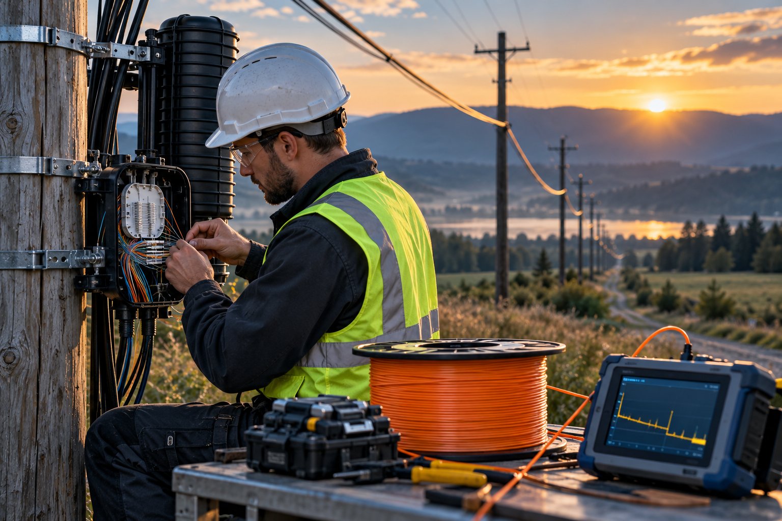
A buyer-focused guide to OTDR acceptance testing for new fiber optic cable installations: what the OTDR proves, which limits to write into the contract, launch fibers, bidirectional testing, wavelengths, report review and common mistakes.
Every fiber optic project reaches the same uncomfortable moment: the cable has been pulled, spliced and terminated, the contractor is asking for sign-off, and you have to decide whether the network you are accepting actually meets the specification you paid for. Visual inspection cannot tell you whether a splice is 0.05 dB or 1.5 dB. An insertion loss meter can tell you the total loss of a link, but not where that loss is located or whether one segment is quietly absorbing most of the margin. This is exactly the gap that OTDR acceptance testing fills.
This guide is written for the people who sign purchase orders and acceptance certificates for optical infrastructure: telecom operators, ISP project managers, utility network owners, data center teams, EPC contractors and distributors who deliver turnkey cabling to their own customers. It explains what an OTDR (Optical Time Domain Reflectometer) can and cannot prove, which parameters belong in your acceptance specification, how a proper field test is executed step by step, and how to read the report the contractor hands you at the end.
What OTDR Acceptance Testing Is — and What It Is Not
An OTDR works like radar for optical fiber. It launches a short pulse of light into the fiber and measures the tiny fraction of light that is scattered back along the entire length. By timing when each echo returns, the instrument builds a curve — the OTDR trace — that shows the attenuation of the fiber in dB/km, the location and magnitude of every splice, connector and bend, and the total length of the link. Where an insertion loss test gives you one number for the whole span, the OTDR gives you a spatial map of the entire route.
That difference is the whole reason acceptance engineers rely on it. When an OTDR trace shows a 0.3 dB event at kilometer marker 4.2, you know precisely where to send a splicing crew. When a segment reads 0.36 dB/km instead of the expected 0.35 dB/km, you know the fiber itself was delivered and installed as specified. When a trace shows a sudden reflective spike near the far end, you know to check the last connector before blaming the cable.
It is equally important to be clear about what an OTDR does not measure. It does not measure the end-to-end insertion loss of a completed link with the accuracy required for commissioning high-speed systems, because it cannot fully capture the loss and reflectance behavior of connectors and does not measure at the actual traffic wavelengths of every transceiver type. It also cannot see through launch conditions without proper launch and tail fibers, cannot detect loss events that produce no backscatter change on a single-direction trace, and it cannot verify connector end-face quality. A professional acceptance program therefore pairs the OTDR with an insertion loss test (LSPM: light source and power meter or a certified OLTS tester) and an end-face inspection. The OTDR answers "where is the plant, and is every event within limits?" The insertion loss test answers "will the link support the intended transmission rate?" Both belong in the acceptance file.
Why Buyers Should Care About the OTDR, Not Just the Datasheet
From a purchasing perspective, the datasheet describes the cable as it leaves the factory; the OTDR describes the cable as it actually exists in your network. Between those two moments sit reel-handling practices, duct congestion, pulling tension, bend radii around corners and closures, splice quality in the field, and hundreds of small decisions made by crews you may never meet. OTDR acceptance testing converts all of that invisible work into measurable evidence.
For a B2B buyer, three practical benefits follow. First, contractual protection: if the trace is captured, timestamped and archived at handover, any degradation found later can be compared against a documented baseline instead of becoming a dispute between installer and supplier with no ground truth. Second, maintenance value: the same baseline traces let your operations team localize future faults to within a few meters, cutting restoration time on buried and aerial routes. Third, supplier accountability: a factory-attenuation claim on paper becomes a verified field value per span, which is the only fair basis for evaluating whether the cable you received performs as quoted.
When Should You Require OTDR Acceptance Testing in a Contract?
In practice, the need scales with route value and fault-repair cost. The following situations justify making bidirectional OTDR testing a contractual deliverable rather than a courtesy:
- Backbone, metro and long-haul spans where a single degraded splice would throttle an entire route.
- Buried and duct routes where excavation for fault-finding is expensive and slow, making an accurate baseline a direct OPEX saving.
- Aerial routes on pole lines and towers — including ADSS and figure-8 self-supporting constructions — where tension, weather exposure and third-party damage make a documented starting condition essential.
- FTTH feeder and distribution segments that will be inherited by an operations team different from the installer.
- Any project where the payment milestone is tied to handover, because the OTDR file is the objective artifact that proves the work was done to spec.
Conversely, short indoor patch-panel-to-patch-panel runs inside a single building are usually verified with an OLTS/insertion loss test plus visual inspection; a full OTDR campaign there often costs more than the risk it retires. Match the test program to the asset, and write that decision into the method statement before crews mobilize.
How an OTDR Actually Builds the Trace
Understanding the physics — at least at buyer level — protects you from accepting a misconfigured test. The instrument fires a light pulse of controlled duration and wavelength into the fiber under test. Two things happen along the way. A small, constant fraction of the light is scattered backward continuously by microscopic density variations in the glass; this Rayleigh backscatter is what makes the trace's sloping baseline, and its slope in dB per kilometer is the fiber's attenuation coefficient. Wherever the light meets a physical discontinuity — a fusion splice, a mechanical splice, a connector, a bend, a crack — part of the power is either absorbed or reflected. Fusion splices absorb a little power without reflecting much, so they appear as small downward steps in the baseline. Connectors and mechanical splices have glass-to-air or glass-to-glass interfaces that reflect, so they appear as upward spikes followed by a step. A break reflects strongly and shows a large spike; the open far end of a fiber produces the terminal reflection that marks the end of the line.
The instrument converts round-trip time into distance using the group index of refraction (IOR) you enter for the fiber. This is why the IOR setting is not a technicality: an incorrect IOR shifts every event location proportionally. If your acceptance contract says "every event must be located within ±5 meters," the tester must use the cable manufacturer's stated effective group index for that fiber, otherwise a crew will dig in the wrong place three years from now.
Pulse width is the second setting that changes what the trace can show. Longer pulses inject more energy, so the trace is cleaner and reaches farther — but events close together merge into one blob because of the instrument's dead zones. Shorter pulses resolve events meters apart but raise the noise floor and shorten the usable range. Professional practice is to test each span at two pulse widths: a short pulse to resolve near-end events and verify individual splice quality, and a longer pulse to characterize the full route length and far-end events. A trace that only exists at one pulse width is an incomplete acceptance record.
The Numbers on the Trace: What Each One Means for Your Acceptance Decision
When the contractor hands you traces, these are the quantities you are actually buying. Each one should appear in the report, and each has a limit in your acceptance specification.
Attenuation coefficient (dB/km)
The slope of the baseline between events. For installed G.652D single mode fiber, a typical field expectation is about 0.35–0.40 dB/km at 1310 nm and 0.20–0.25 dB/km at 1550 nm, but the binding values are always the cable datasheet values plus any allowance your project spec grants for splices, connectors and aging. What the OTDR check protects you against is a section that comes in well above the curve — evidence of over-tension, a kinked segment, a degraded splice, or fiber that does not match the reel labels. Always confirm the acceptance threshold against the actual product specification sheet rather than treating any printed number here as a guaranteed field value.
Event loss (dB) — splices and connectors
The step height at each event. Industry-typical acceptance limits that appear in project specs are 0.10 dB average (or 0.15–0.30 dB maximum) per fusion splice and roughly 0.30–0.75 dB per mated connector pair depending on the system budget; APC connectors are additionally judged on reflectance. These are common reference figures only — your own specification, the transmission system vendor's requirements and the cable datasheet always take precedence.
Reflectance (dB) and optical return loss (ORL)
Reflective events matter because reflected light destabilizes laser transmitters and degrades high-bit-rate links. A mechanical splice might reflect at −40 to −55 dB, a physical-contact UPC connector around −50 dB, and an APC connector around −65 dB or better, again as typical figures to be confirmed against the transceiver and connector specifications. If your network runs high-speed single mode optics over the span, reflectance limits on the trace are not optional nice-to-haves; they are acceptance criteria.
Dead zones: event and attenuation
After a strong reflection, the detector needs distance to recover before it can measure again. The event dead zone is the minimum distance at which two reflective events can be told apart; the attenuation dead zone is the distance after which a loss event can be measured accurately. Typical OTDR figures range from a few meters to tens of meters depending on the instrument and pulse width. The practical consequence for buyers: put launch and tail fibers on the test (covered below), and require short-pulse traces so that splices near closures are individually resolved rather than merged.
Length
The measured route length should match the design and the cable markings within a small tolerance, accounting for cable overlength in ducts, slack loops and the difference between cable length and fiber length (fiber inside a tube runs slightly longer than the jacket because of the stranding lay). A length mismatch is often the first clue that a section was rerouted, that slack was left in an undocumented location, or that the wrong reel was installed.
Which Test Wavelengths Should You Specify?
Single mode field acceptance is normally specified at both 1310 nm and 1550 nm, because the two wavelengths fail in different ways. At 1310 nm, attenuation per kilometer is naturally higher and small bends matter less; at 1550 nm the fiber is intrinsically lower-loss, which makes any excess bending loss jump out of the trace. A macrobend that is invisible at 1310 nm can cost 1 dB or more at 1550 nm — so if your program only tests one wavelength, bend damage can pass undetected. Many specifications add 1625 nm (or 1650 nm) testing, partly because it is even more bend-sensitive and partly because it can be performed on live routes with appropriate filtering, making it the standard wavelength for later maintenance fault-location without disturbing traffic.
Multimode spans are tested at 850 nm and 1300 nm with a launch condition matched to the standard in force for the link class. The same buyer logic applies: name the wavelengths in the acceptance specification, because a trace file without wavelength metadata cannot be compared against any limit.
Why Bidirectional Testing Matters — and Why Single-Direction Traces Cause Disputes
A loss event reads differently depending on which end you shoot from. The reason is backscatter asymmetry: if the fiber segment after a splice scatters more light than the segment before it (because the two fibers differ slightly in backscatter coefficient, even within the same specification), the OTDR will show an artificially low loss — sometimes even a "gainer," where the trace steps upward through a splice that is really adding loss. Shot from the opposite end, the same splice reads artificially high. The arithmetic average of the two directions is the true loss.
The practical rule for acceptance is simple: every span is tested from both ends, and every event is evaluated on the averaged value. This is not gold-plating; it is the difference between a contractor claiming a splice passes at 0.02 dB from one direction and the same splice honestly measuring 0.25 dB averaged. If your acceptance procedure does not state bidirectional testing explicitly, you are leaving that ambiguity open — and ambiguity at handover always resolves in favor of whoever did not specify it.
Bidirectional testing also doubles as a health check on the fibers themselves. Averaged attenuation coefficients that match between directions with clean slopes indicate healthy plant; a direction-dependent anomaly localized to one section usually points to a bend or a stress point that deserves a closer look before sign-off.
Launch and Tail Fibers: The Detail That Makes or Breaks the Measurement
An OTDR cannot measure what happens in its own first few meters: the connector at the instrument port creates a large reflection, followed by the event and attenuation dead zones. Any splice or connector within that blind region is invisible or misread. The standard fix is a launch fiber (also called a pulse suppressor or dead-zone fiber) — a known-good spool of fiber, typically 500 to 2000 meters for acceptance work, connected between the instrument and the link under test. With a launch fiber in place, the trace baseline is established before the actual link begins, and the entry connector of your link becomes an ordinary measurable event.
A tail fiber on the far end does the same job for the exit connector, and it also guarantees that the far-end connection appears as a discrete event rather than merging into the terminal reflection. During measurement, you then place the trace cursors after the launch-fiber event and before the tail-fiber event, so the reported loss and length describe only the cable you are accepting.
Three contract-relevant consequences follow. First, the launch and tail fibers must be on the test plan; "OTDR tested" without them usually means the first and last 50 meters of your plant were never actually verified. Second, the launch and tail events are excluded from the link's event limits but must still be identifiable in the report so the reviewer can see they were used. Third, launch fibers should be of the same fiber type and, ideally, length-matched within the project; a mismatched launch fiber distorts the very first event measurements — the ones closest to your equipment, where losses matter most.
A Step-by-Step OTDR Acceptance Procedure You Can Put in Your Method Statement
The following sequence reflects common field practice for single mode plant and can be adapted into your project's inspection and test plan. Quantities marked "typical" must be reconciled with your own specification and the product datasheets before they become binding limits.
Step 1 — Freeze the acceptance criteria. Before testing, confirm in writing: test wavelengths (typically 1310/1550 nm, plus 1625/1650 nm where required), bidirectional requirement, per-event loss limits (typical fusion splice averages around 0.10 dB), attenuation coefficient limits per fiber type, reflectance limits where applicable, and the report format. The criteria come from your project spec, the transmission system requirements and the cable datasheet — not from the contractor's habits.
Step 2 — Verify the test set. Confirm the OTDR calibration is current, the launch and tail fibers are the agreed lengths and fiber types, the IOR and backscatter coefficient settings match the installed cable, and connectors on the test leads are clean and inspected. A dirty launch connector quietly inflates every measurement on the trace.
Step 3 — Clean and inspect every test interface. End-face contamination is the leading cause of false failures and unstable readings. Inspect and clean the OTDR port, launch/tail connectors, and the link's test access connectors before each measurement; re-inspect after any disconnection.
Step 4 — Test each fiber from End A with short and long pulse widths. Acquire the trace with the short pulse first to resolve individual events and the entry region; then acquire with the longer pulse for full-route characterization. Name files consistently — span ID, fiber number, wavelength, pulse width, direction, date — because a report you cannot trace back to a fiber is not an acceptance document.
Step 5 — Repeat from End B. Move the instrument to the far end, using the same discipline, and acquire the same set of traces in the reverse direction.
Step 6 — Analyze against the frozen criteria. For each fiber: confirm the length against the design; confirm baseline attenuation against the limits; evaluate each event on the bidirectionally averaged value; flag any reflective event above the reflectance limit; and list every event with its location, loss and classification. Most analysis software automates the averaging, but a human engineer should still review event classification — software happily labels a cracked bend as a "non-reflective event" and moves on.
Step 7 — Remediate and re-test. Any event beyond limits triggers re-polishing, re-termination or re-splicing, followed by re-testing of the affected fiber in both directions. Acceptance is per fiber, not per route: one bad fiber in a 96-core cable is a failed acceptance for that fiber until corrected.
Step 8 — Archive the baseline. Deliver the raw trace files (in the instrument's native format plus universal .sor files), the analysis summary, and the instrument/settings record. This archive is what turns the handover package into a maintenance tool for the next decade.
Writing Pass/Fail Criteria That Survive a Dispute
A acceptance threshold does its job only if it is specific, sourced and realistic. The table below collects industry-typical reference values that appear in many field specifications; treat every row as a starting point to reconcile against your project specification, the transmission equipment requirements and the actual cable datasheet, not as guaranteed or universal limits.
| Parameter | Typical acceptance reference | Source to reconcile against |
|---|---|---|
| Fiber attenuation (installed G.652D) | ≈0.35–0.40 dB/km @1310 nm; ≈0.20–0.25 dB/km @1550 nm | Cable datasheet + project allowance |
| Fusion splice loss | ≈0.10 dB average, ≈0.15–0.30 dB max per splice | Project spec / splicer performance |
| Mated connector pair loss | ≈0.30–0.75 dB per pair | Link budget / OLTS results |
| Connector reflectance (UPC) | ≈−50 dB or better | Connector & transceiver spec |
| Connector reflectance (APC) | ≈−60 to −65 dB or better | Connector & transceiver spec |
| Route length deviation | Within small tolerance of design, documented | Route design + cable overlength plan |
| Test directions | Bidirectional, averaged | Project method statement |
Three drafting rules make the difference between a workable clause and a future argument. First, state whether the limit applies to the averaged bidirectional value or to each direction — averaged is the technically correct choice and the common one. Second, tie attenuation limits to the specific fiber type and wavelength installed, because a single "≤0.4 dB/km" figure cannot govern a route mixing G.652D backbone fiber with bend-optimized fiber. Third, define what happens on marginal results: an events-between-limits band (for example, results within 10% over the limit requiring engineering review rather than automatic rework) prevents both gold-plating and silent waivers. None of these numbers should be copied into a contract without checking the governing documents; the datasheet delivered with the reels on your project is the authoritative reference for the fiber's optical performance.
The Most Common OTDR Testing Mistakes — and How They Inflate Your Risk
Acceptance engineers see the same failure patterns repeatedly. Knowing them turns you from a passive recipient of a PDF report into a competent reviewer of the evidence.
- Missing launch or tail fiber. The near-end blind zone then hides the first connectors — frequently the ones carrying the highest loss in the link. If the trace starts at zero meters with a huge front-end reflection and no launch event, the record is incomplete.
- Wrong IOR or backscatter settings. Every distance is shifted and every loss is skewed. Cross-check the reported route length against the known duct length before trusting any event location.
- Single-direction only. Gainers and hidden losses distort the event list; the averaged bidirectional value is the only defensible number.
- One pulse width only. A long-pulse trace can merge adjacent splices in a closure into one apparent event, hiding an out-of-spec splice behind a passing average.
- Ghost events. Strong far-end reflections can bounce inside the fiber and reappear as phantom events. Ghosts disappear when the pulse width or acquisition settings change — a technician should recognize and re-test rather than document a phantom.
- Dirty connectors at the test access. Intermittent or inflated readings that waste crew hours; end-face inspection should precede every acquisition.
- Accepting summary spreadsheets without raw traces. A spreadsheet cannot be re-analyzed. Acceptance evidence means the .sor files, not just conclusions.
- Testing at the wrong wavelength for the failure mode. Skipping 1550/1625 nm leaves macrobend damage undetected, which is exactly the damage that cable handling errors cause.
What the Acceptance Report Should Contain
The deliverable at handover is a package, not a stack of screenshots. A complete OTDR acceptance file includes: the project and span identification; the instrument make, model, module and calibration status; the test settings used (wavelengths, pulse widths, IOR, backscatter coefficient, ranges, averaging time); launch and tail fiber lengths; the raw bidirectional trace files per fiber in a standard format; the event tables with averaged losses and classifications; the pass/fail disposition of every fiber against the frozen criteria; and the remediation record with re-test traces for any corrected event. Ask for this list by name in the contract annex. Contractors are not hiding anything by delivering less — they simply deliver what was specified, so specify the full package.
What the OTDR Finds — and What It Cannot
Used correctly, the OTDR verifies fiber continuity, locates every splice and connector with meter-level accuracy, quantifies each event's loss and reflectance, measures true route length, exposes macrobends and stress points via wavelength-dependent loss, and establishes the maintenance baseline for future fault localization. It does not verify connector end-face cleanliness and geometry (that is microscope territory), it does not by itself certify that a completed link meets the loss budget of a specific transmission rate (that is the insertion loss test with an OLTS or source-and-meter set), it cannot see through splitters in PON plant beyond the splitter in any usable detail, and it cannot predict future reliability — a splice at 0.05 dB today can still fail in three years if the closure was sealed poorly. Acceptance programs that combine OTDR + OLTS + end-face inspection + a documented installation record cover all four blind spots. Budget accordingly: the marginal cost of the other two tests is small next to the cost of re-mobilizing a crew.
How Your Cable Supplier Should Support Acceptance Testing
OTDR acceptance testing is usually executed by the installation contractor, but the cable supplier directly influences how smoothly it goes. When you evaluate suppliers for a project that includes acceptance testing, the following points are worth asking about explicitly:
- Consistent, documented fiber parameters. The tester needs the correct group index and backscatter coefficient for the installed fiber; the supplier should state these in the datasheet so the contractor does not guess.
- Factory test data on every reel. Attenuation per reel as measured at the factory gives the acceptance team a reference baseline: if reel 37 measured a certain attenuation at the factory, the installed span should read consistently with it. This is what allows a field anomaly to be attributed to installation or to product, quickly and fairly.
- Reel-by-reel length marking. Route-length checks against cable markings are only meaningful if printed lengths are accurate and sequential along the route.
- Prompt technical support for anomalies. When a span reads high, the acceptance team needs the datasheet values, the manufacturing batch context and a responsive engineer — not a ticket queue.
- Contract-friendly warranty terms. Warranty conditions should be written down plainly. Nexora, for example, warrants its fiber optic cable products for 12 months from shipment date; the specific scope of what is covered is defined in the sales contract, and buyers should confirm the warranty wording as part of procurement rather than assuming it.
The division of responsibility is worth stating plainly because it prevents the most common commercial deadlock after a failed acceptance: the supplier is responsible for the cable conforming to its datasheet and the contract; the installer is responsible for workmanship within the limits of the method statement; the OTDR proves which one — if either — introduced an event. A trace showing one bad splice at a closure answers a question that would otherwise take weeks of correspondence.
Frequently Asked Questions
Do we need OTDR testing on every fiber, or is sampling acceptable?
Sampling is a compromise, not a best practice. Any fiber that was not tested is a fiber whose splice losses, bends and length were never verified. On backbone and high-value routes, test every fiber bidirectionally. Where budgets genuinely force sampling, sample systematically — for example all fibers in a defined percentage of closures plus every fiber in the highest-risk sections — and state the sampling plan in the contract, so that untested fibers are a known, accepted risk rather than an oversight.
Can we use the contractor's OTDR, or should we require our own?
The instrument matters less than the settings, the discipline and the evidence. A contractor's calibrated OTDR with proper launch fibers and full raw-trace delivery is acceptable for most projects. For the largest builds, owners sometimes add independent spot-check testing at random spans, which costs little and discourages shortcuts. If you spot-check, do it before final payment, not after.
What is the difference between acceptance testing and commissioning testing?
Acceptance testing verifies the passive plant against the contract: attenuation, events, length, reflectance. Commissioning verifies that the active transmission system — the optics, the equipment, the actual channels — performs over that plant. They overlap in evidence but answer different questions, and both should appear in the handover file.
Why did a splice show as a "gainer" in one direction?
A gainer means the fiber after the splice backscatters more light than the fiber before it, so the trace appears to rise through the event. It is an artifact of comparing backscatter levels between two slightly different fibers, not free performance. This is precisely why the acceptance value is the average of both directions.
How long does OTDR acceptance testing take?
With trained crews, a single fiber test in one direction takes minutes, but the full program — setup, cleaning, both directions, two pulse widths, analysis and documentation — typically means the schedule is driven by fiber count and access logistics. For planning purposes, teams usually schedule acceptance as its own mobilization rather than an afterthought at the end of a splicing shift, because rushed testing produces exactly the incomplete evidence that causes re-testing later.
What file format should we require for the traces?
Require the instrument's native files plus the universal Bellcore .sor format. Native files preserve every setting detail; .sor files guarantee that any engineer with any analysis tool can open the evidence in ten years. A PDF summary alone is not an acceptable acceptance record.
Can an OTDR test be done on a live network?
Yes, at 1625 or 1650 nm with a wavelength-filtered port that blocks the working wavelengths from reaching the detector. This is standard practice for maintenance fault-location on in-service routes. For initial acceptance, however, the plant should be dark, because acceptance criteria and acquisition settings assume it.
Does OTDR testing replace the insertion loss test?
No. The OTDR maps and locates events; the insertion loss test proves the end-to-end loss the transmission system will actually see, measured with a light source and power meter in both directions. Acceptance specifications normally require both, and if one number has to explain a system outage margin problem, it is usually the OLTS result.
Preparing the Route and the Crew Before the Tester Arrives
A large share of acceptance delays has nothing to do with the OTDR itself. The single biggest schedule factor is access: every closure, patch panel and test point along the route must be reachable, openable and safe on the test day. A program that plans testing while crews still have splicing equipment in the same manholes spends half its time waiting for itself. Build the test window into the construction schedule, and treat it as a distinct activity with its own crew, its own access permissions and its own weather contingency.
Three preparation items deserve a line in the method statement. First, agree the test access points in advance: testing is performed from equipment rooms, splice closures or connector panels, and the plan should name where each span starts and ends physically. Second, confirm fiber identification discipline. On a 96-core cable, the trace files are only as useful as the labeling that connects fiber 41 in closure 7 to the design drawing; crews should establish the color-code and port mapping before testing begins, not reconstruct it from memory afterward. Third, decide how temporary events — slack-loop storage, test cords, mid-span access — will be handled in the report, so that the permanent baseline distinguishes genuine plant events from test artifacts.
Crew competence is the remaining variable. The instrument will happily save a misconfigured trace; only an operator who understands dead zones, IOR settings and bidirectional averaging produces evidence worth archiving. For projects where acceptance results carry payment milestones, a short alignment session between the owner's engineer and the testing crew — walking through the frozen criteria and the file-naming convention — routinely pays for itself by eliminating re-tests.
How to Review an OTDR Report When You Are Not the Test Engineer
You do not need to operate the instrument to review the evidence competently. Open the summary and check five things in order. Does every fiber in the route appear, with both directions and both pulse widths? Does the reported length of each span match the route design within the documented tolerance? Do the averaged attenuation coefficients sit under the limits tied to the installed fiber type and wavelength? Is every event listed with a location, a classification and a disposition — no unexplained "unknown" events? And are the raw trace files attached, not merely referenced? A report that answers all five cleanly has, in practice, been produced by a crew that also tested properly; the paperwork discipline and the measurement discipline come from the same place.
Key Takeaways for Buyers and Project Owners
- Write OTDR acceptance testing into the contract: wavelengths, bidirectional testing, per-event limits, report format and raw .sor delivery.
- Require launch and tail fibers on every test — without them the first and last sections of your plant are unverified.
- Evaluate every event on the averaged bidirectional value; single-direction numbers invite gainers and disputes.
- Test at 1310 and 1550 nm minimum (plus 1625/1650 nm where specified) so bend damage cannot hide.
- Accept per fiber, not per route, and archive the baseline — it is the reference that makes every future fault call faster and cheaper.
- Pair the OTDR with insertion loss and end-face inspection so the acceptance file covers what the trace cannot see.
OTDR acceptance testing is not a formality appended to a splicing job; it is the mechanism that converts your cable investment into documented, maintainable, warrantable plant. Specify it precisely, review the evidence critically, and the same traces that earned the contractor their payment certificate will keep earning their keep every time your operations team needs to find a fault at kilometer 41.6 instead of excavating three kilometers of duct.
Planning a fiber optic cable project that will include OTDR acceptance testing? Nexora manufactures outdoor loose-tube, ADSS, figure-8, indoor tight-buffered and distribution fiber optic cable, along with pigtails, patch cords and adapters, with OEM/ODM support for project-specific requirements. Every cable is delivered with datasheet parameters that your acceptance team can load directly into the test set, and our team can align factory test documentation with your acceptance plan. Warranty: 12 months from shipment date. Contact the Nexora team to discuss fiber specifications, reel documentation and delivery for your next route.