
A practical emergency repair planning guide for network operators: common causes of fiber optic cable damage, fast fault location, first-hour response steps, temporary versus permanent repair choices, buried and aerial repair procedures, and what to stock in an emergency repair kit. All performance values are typical industry figures; confirm against datasheets. Warranty: 12 months from shipment date.

A severed fiber optic cable is one of the few events in a network operator's day that turns a routine schedule into an incident. Within minutes of a fiber cut, transport equipment alarms across your footprint, customer complaints start arriving, and your SLA clock is running. Unlike most equipment faults, a cable break cannot be fixed remotely, cannot be worked around with a software patch, and often cannot even be reached quickly because the damage sits in a trench, a duct, or a pole line twenty kilometers from your nearest crew.
Planned maintenance and unplanned restoration are different disciplines. In planned work, you choose the date, the crew, the traffic windows, and the splicing plan in advance, and you test everything before closing out. In restoration, you inherit the circumstances: weather, daylight, traffic, landowners, other utilities already in the hole, and a route you may have to locate from paper records. The organizations that recover fastest are not necessarily the ones with the best splicers; they are the ones with a written, rehearsed response plan and the right materials staged before the cut happens.
This guide is written for B2B buyers, telecom contractors, and ISP and network operations teams who are responsible for keeping links up. It walks through the causes of fiber damage, how to locate a fault quickly, what the first hour of a restoration should look like, when to accept a temporary fix, and what an emergency repair kit should actually contain. The goal is a repeatable playbook you can hand to your ops team, not a collection of general advice.
Why Does Fiber Optic Cable Damage Deserve a Response Plan of Its Own?
The business case is straightforward. A single fiber pair can carry traffic for thousands of end users, so one backhoe strike can take an entire business park, a mobile backhaul ring, or a data center interconnect offline at once. For enterprise-facing operators, downtime clauses in customer contracts start accruing penalties from the moment service is lost, and the revenue at risk over a four- or six-hour outage usually dwarfs the cost of the repair itself, which might be a few hundred meters of cable and a day of labor.
It helps to distinguish damage from aging. Cable degradation over decades of service shows up gradually as rising attenuation, water ingress slowly working through sheath defects, and fiber fatigue; that is a lifecycle planning problem with months or years of visibility. Sudden damage, by contrast, gives you no lead time at all. If you are still deciding when your installed base should be replaced, that is a separate exercise, and we cover it in detail in our article on how long fiber optic cable lasts and when to plan for replacement. The response plan discussed here is for the events that take you from healthy to dark in one second.
Why does preparation beat improvisation so decisively in restoration work? Because every decision made during an outage is made under pressure, with incomplete information, by people who are also juggling customer updates. If nobody has decided in advance who authorizes a temporary repair, which spare cable types are stocked, or where the OTDR access points are, you will spend the first critical hours on coordination rather than on the fiber. Operators who rehearse their response, even as a simple tabletop exercise once a year, routinely cut their restoration time substantially compared to those who wing it. The plan does not need to be elaborate; it needs to exist, be written down, and be known by more than one person.
There is also a procurement angle. The materials you need at 2 a.m. are the materials you either bought last year or did not. That is why this article ends with a concrete emergency kit list: it is a shopping list you can build into your normal spares procurement, not something you can conjure up mid-outage.
What Are the Most Common Causes of Fiber Optic Cable Damage in the Field?
Knowing the likely causes tells you where to look first and how to design against repeat incidents. In practice, the distribution is heavily skewed toward a handful of mechanisms.
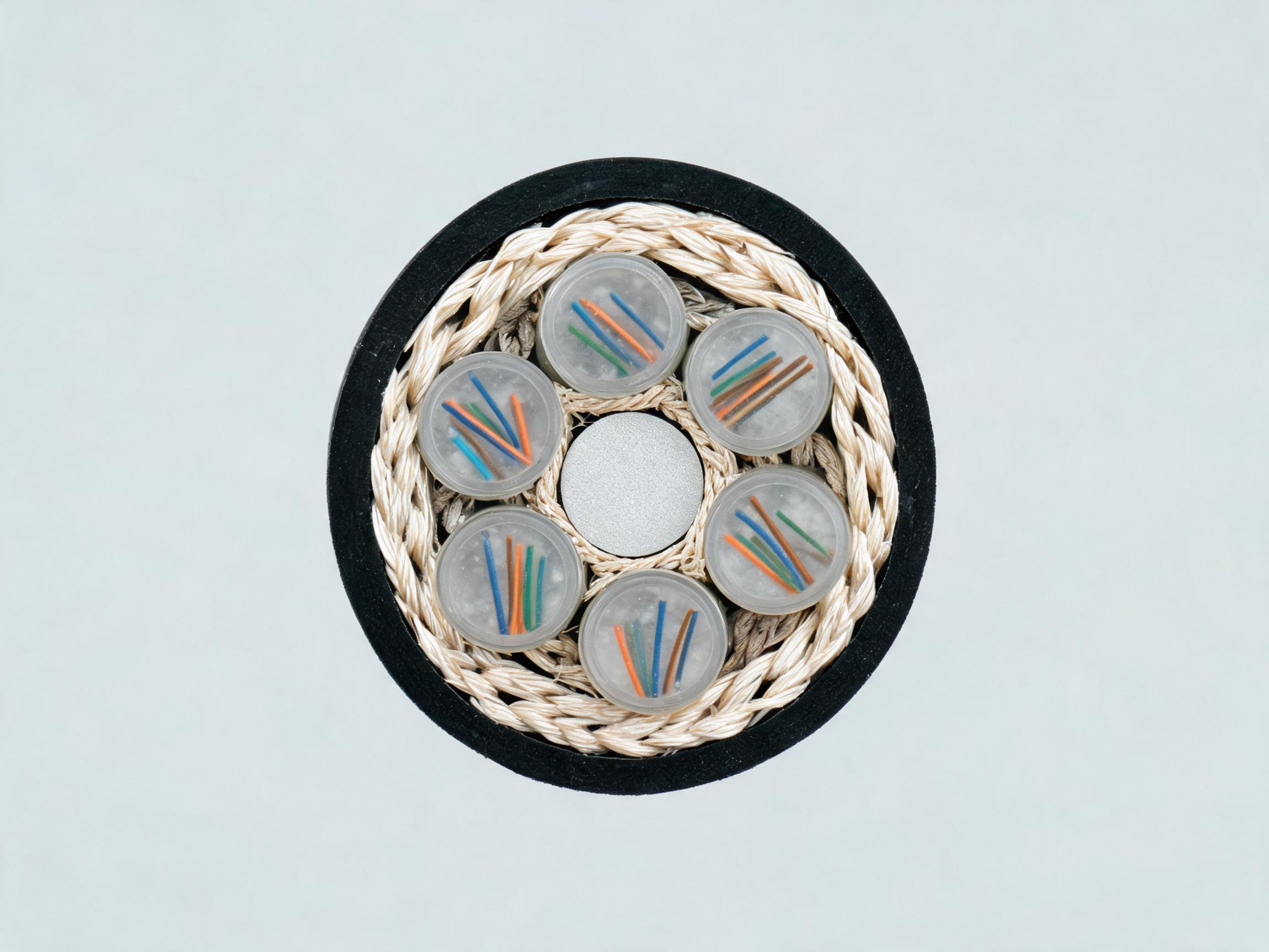
Third-party excavation is by far the most common cause of damage to buried cable. Other utilities digging without accurate records, construction crews hitting a route nobody flagged, even a farmer driving a fence post through a shallow run. Most buried cuts are clean breaks at a single point, which is actually good news for restoration: you splice in a re-entry section and move on. The harder cases are crush damage, where a rock or machinery has deformed the cable without severing it, because the fault location is fuzzier and the damaged section may be longer than it looks from outside.
Rodent damage is the quiet chronic problem. Squirrels, rats, and other gnawing animals chew through polyethylene sheaths to sharpen teeth or because of the odor of some sheathing compounds, and they favor certain routes, especially in ducts and ceilings. The initial breach may not take the link down at all; water gets in over months, attenuation creeps up, and one winter freeze turns it into an outage. This is a significant part of the case for armored cable on exposed and rodent-prone routes; our buyer's guide on when to use armored fiber optic cable covers that trade-off in depth. For buried routes generally, see our guide on installing direct buried fiber optic cable, which covers depth and marking practices that prevent many of these strikes in the first place.
On aerial routes, the two dominant mechanisms are excessive tension and tree fall. Pulling aerial cable with too much force during installation can strain the fibers beyond their proof-test level and cause delayed failures months later. A falling limb, ice loading, or a vehicle strike on a pole applies sudden mechanical shock that snaps fibers or crushes the cable at a single span. Water ingress through a damaged sheath is its own failure mode: fiber itself does not absorb water the way copper does, but water accelerates attenuation growth over time and can freeze in loose tubes, microbending the fibers. Fire and heat, from brush fires or a hot duct environment, melt sheaths and damage coating. Lightning strikes punch through metallic elements and can shatter fibers over a run of several meters, which means the damaged section may be too long to splice and must be replaced outright. Vandalism and copper-style cable theft mostly target accessible above-ground runs; fiber has little scrap value, but thieves do not always know that, and the damage they leave behind is the same as any other cut.
| Damage cause | Typical affected routes | Typical first symptom | Best detection method |
|---|---|---|---|
| Third-party excavation | Direct buried and duct routes near construction zones | Sudden total loss of signal on multiple fibers | OTDR distance-to-fault plus visual check of active construction along the measured point |
| Rodent gnawing | Duct runs, ceilings, aerial spans in vegetated areas | Gradual attenuation increase, then intermittent loss | OTDR trend comparison against baseline records; physical sheath inspection |
| Excessive pulling tension / tree fall (aerial) | Aerial spans, pole lines | Loss on one or more fibers, sometimes delayed failure weeks later | OTDR, plus span-by-span visual patrol after storms |
| Water ingress | Buried and duct cable with sheath defects | Rising loss over weeks or months; loss spikes after rain or freezing | OTDR monitoring against acceptance baseline |
| Fire / heat | Buried routes in brush areas, tunnels, industrial ducts | Loss of signal over a contiguous section | OTDR section loss profile; visual inspection of affected area |
| Lightning | Buried and aerial routes with metallic elements, exposed terrain | Multi-fiber loss after a storm, often over several meters | OTDR; expect replacement rather than splice |
| Vandalism / attempted theft | Accessible above-ground runs, walls, poles | Sudden loss; visible cut ends at the site | Visual inspection once OTDR pinpoints the location |
How Do You Detect and Locate the Damage Quickly?
Detection is usually the easy half. If the damaged route carries active services, your transport equipment will tell you within seconds: loss of signal alarms, RX power collapse on a line card, or a ring protection switch indicating a fiber failure. If the cable is dark or only lightly used, damage often goes unnoticed until someone turns the link up or a scheduled OTDR patrol finds rising loss. This is one of the arguments for periodic OTDR baseline checks on dark fiber; a cable that has been quietly chewed through its sheath for six months should not surprise you when it finally fails.
Once you know a fault exists, coarse localization starts with your route maps and a phone. If the OTDR says the fault is 7.4 km out from your central office, and your records show construction activity near the 7 km mark, you have likely found your backhoe before anyone leaves the depot. Cross-checking with other utilities pays off more often than crews expect: call the local water, gas, and power operators and ask whether they have crews in the area. Someone usually knows about a hole in the ground. On aerial routes, a simple drive-along patrol of the measured section frequently finds the fallen limb or the slack span with the naked eye.
The OTDR is your precision instrument, but it needs to be used with care during an emergency. The distance-to-fault figure depends on the group index (IOR) setting; if your OTDR is configured with a group index that does not match the actual fiber in the cable, the reported distance can be off by a surprising margin, sometimes tens of meters, which on a buried route means digging in the wrong place. A two-way measurement, testing from both ends and averaging, cancels out much of this error and also helps distinguish real events from connector reflections. Remember that OTDRs have dead zones after strong reflections, so a fault sitting just past a patch panel or a good splice can hide from the trace. Ghost events from reflections along the route can also mimic faults. If you want the full method, including how to set wavelength, pulse width, and how to interpret events, our dedicated article on using an OTDR to accept a new fiber optic cable installation walks through it step by step.
For short links and for confirming a visible break, a visual fault locator earns its place in every restoration kit. A VFL injects visible red light into the fiber; at a break or a sharp bend, the light leaks out and you can see the glow through the jacket or at the exposed fiber end. It will not carry through kilometers of cable, so it is a last-few-hundred-meters tool, but it is invaluable for confirming exactly which fiber and exactly which point is damaged once the cable is opened, and for finding bad connectors in a patch panel under time pressure. Our article on troubleshooting with a VFL covers the practical technique. Once the physical fault is fixed, a proper insertion loss test with a light source and power meter is the acceptance procedure; the detailed method is covered in our guide to testing a fiber optic link with a light source and power meter.
One more practical point: know your access points before the emergency. Where can you actually inject the OTDR pulse? A pigtail or patch panel at a hut, a splice closure with spare fiber, a demarcation point. If the only OTDR access is at one end of a 40 km route, your localization will be coarser and slower than if you can test from a mid-route access. Marking these on your route documentation is a five-minute task that saves hours during an outage.
What Should the First Hour of a Restoration Look Like?
The first hour decides whether you finish in four hours or twelve. Here is a playbook that experienced restoration teams converge on, roughly in this order.
First, confirm the service impact. Which customers and services ride the affected fiber? Pull the route's traffic inventory and check whether your protection scheme has already rerouted anything. Do this before you dispatch anyone, because the answer changes everything else: a dark pair cut in a rural spur is a work order; a backhaul ring carrying enterprise circuits is an incident with executives on the call.
Second, use whatever redundancy you have designed in. If the affected segment is part of a ring or has an alternate path, switch traffic now, before the repair. This is the single most valuable move available, and it only works if the alternate path is real, tested, and has spare fiber capacity. Operators who discover during an outage that their "backup" route was cut two months ago and never fixed learn this lesson expensively. If you have designed ring protection, verify the alternate path periodically as part of planned maintenance.
Third, dispatch the right crew with the right kit in one go. The most common first-hour failure is dispatching a crew that then has to return for the fusion splicer, the spare closure, or the correct cable type. Your emergency kit (detailed in the next section) exists precisely so the truck can be loaded in minutes from a known checklist rather than from memory. Include the OTDR or confirm the crew has one, plus the route documentation and access point map.
Fourth, notify stakeholders in parallel with dispatch, not after. Customers with SLAs, the excavation authority if third-party digging is involved (you may need their cooperation, and in many jurisdictions their records), the other utilities in the area, and internal management. A short factual update, what is down, what is the current estimate, next update time, is far better than silence. Silence generates escalations that consume your team's attention.
Fifth, set an internal restoration target and a decision point. Decide in advance under what conditions you will accept a temporary fix versus holding out for a permanent splice, and set a checkpoint time, say two hours in, at which the field lead must report the situation and confirm the plan. Without a checkpoint, restoration work has a way of drifting.
| Response step | Owner | Typical target time |
|---|---|---|
| Confirm service impact and affected customers | NOC / operations desk | Within 15 minutes of alarm |
| Switch or reroute traffic onto protection / alternate fiber where available | NOC with transport engineering | Within 15–30 minutes, automated if designed for it |
| OTDR localization and route cross-check | Field lead or NOC with remote test access | Within 30–45 minutes |
| Crew dispatched with full restoration kit and documentation | Dispatch / field operations | Within 45–60 minutes of fault confirmation |
| Stakeholder notifications issued with first estimate | NOC / account management | Within 60 minutes |
| Internal checkpoint: confirm plan, temporary vs. permanent decision | Field lead with operations manager | Around the 2-hour mark, or earlier if site conditions are clear |
The times in the table are typical values drawn from common operator practice and will vary with your SLA commitments, crew coverage, and route geography; set your own targets against your contractual obligations. What matters is that the targets exist and the ownership is unambiguous before the phone rings.
One technical input into the first-hour decisions is the link loss budget. Knowing the designed margin for the affected link tells you immediately whether a temporary repair with slightly higher loss will still carry service acceptably, or whether only a clean fusion splice will do. If your design documentation includes the link loss budget calculation, your field lead can make that call on site with numbers instead of guesswork.
Temporary Fix or Permanent Repair: Which Should Come First?
The honest answer: it depends on the service impact, and you should decide the policy in advance rather than during the outage. There are three levels of restoration available to a field crew, and they differ enormously in speed and optical quality.
Mechanical splicing is the fastest permanent-ish option: the fiber ends are aligned in a precision V-groove and held with index-matching gel, no fusion machine required. A crew can complete a mechanical splice in a few minutes per fiber once the cable is opened and prepared. Pre-terminated restoration cable is even faster in one sense: you cut out the damaged section and insert a factory-terminated patch or splice-in section with connectors, trading splice quality for connector pairs and extra attenuation. Fusion splicing, arc-welding the fiber ends, gives the lowest loss and the most durable joint, but the splicer cycle, stripping, cleaning, cleaving, splicing, and protecting each fiber, adds up when you are splicing a 96-fiber cable: hours of careful bench work, possibly in rain, in the dark, at the side of a road.
A pragmatic policy many operators use: restore service fast with mechanical splices or a pre-terminated section if the affected link has meaningful traffic, then schedule a permanent fusion splice re-entry within days or weeks as planned maintenance. For dark or low-value pairs, or when the crew is already on site with time available, go straight to fusion. The exception is multi-fiber cuts on critical routes, where restoring all fibers with mechanical splices and then re-splicing permanently later is often faster overall than doing everything by fusion in one go.
| Approach | Typical time on site | Typical added loss per joint | When appropriate |
|---|---|---|---|
| Mechanical splice | A few minutes per fiber once cable is prepared | Typically around 0.1–0.3 dB; confirm against the splice datasheet | Fast temporary restoration; small fiber counts; emergency kits |
| Pre-terminated restoration cable section | Fastest for multi-fiber cuts if a matching section is stocked | Connector pairs typically around 0.3–0.5 dB each; confirm with datasheet | Long damaged sections; crews without splicer access; dark hours |
| Fusion splice | Slower; multi-fiber splices take hours of careful work | Typically around 0.02–0.05 dB per joint for single mode | Permanent repair; high-count cables; low-loss budget links |
Two cautions on temporary fixes. First, mechanical splices and connectors add loss and reflectance; on a link that was already near its loss budget, a chain of temporary joints may push RX power below the receiver threshold, and then your "fast fix" does not actually restore service. That is why the loss budget documentation matters. Second, mechanical splices with index-matching gel are more sensitive to temperature cycling and vibration over time than fusion joints, so treat them as interim, not final, on buried and aerial routes. Our full comparison of the two termination methods, including cost per joint and skill requirements, is in the article on fusion splicing versus mechanical splicing.
Whatever you choose, record what was done: location, method, fiber numbers, and loss readings. The next crew to open that closure, possibly years later, needs to know there are mechanical splices in the tray that should be replaced.
What Should a Fiber Optic Emergency Repair Kit Contain?
An emergency kit is the physical embodiment of your response plan, and it is built from ordinary procurement decisions made months earlier. The contents below reflect what restoration crews actually reach for, organized by function. Note that the holding quantities are typical industry practice for small and mid-size operators; scale them to your route inventory and confirm against your own project requirements.
The foundation is spare cable that matches the routes you operate. At minimum, keep drums of your standard outdoor cable types, the same fiber counts and construction as your main deployed routes, in short restoration lengths (commonly a few hundred meters to a couple of kilometers) plus at least one longer drum. If your routes include a mix of constructions, such as standard loose-tube, armored, and self-supporting aerial, the kit should include each, because a splice between mismatched constructions is possible but slow and awkward at 3 a.m. Storage matters too: cable that has been sitting outdoors on a rack for three years with a sun-damaged sheath is not a restoration asset, so keep spares indoors per proper warehouse practice.
Splice consumables come next. Spare splice closures, dome type for buried and aerial, inline type as your deployments dictate, because a cut cable needs not just a splice but a home for it, and the old closure may be damaged or inaccessible. You need fusion splicer consumables: splice protectors (the heat-shrink sleeves that protect every fusion joint), strippers, cleaver blades in good condition, isopropyl alcohol and lint-free wipes, and marking supplies. Mechanical splice kits as the fast-temporary option described above. Pigtails and patch cords for restoration patching at panels and closures, plus a stock of adapters to match your deployed connector types. Finally, test access: a VFL for every crew and OTDR access arrangements, whether that is a portable OTDR in the kit or agreed remote test head locations.
| Item | Why it belongs in the kit | Typical holding guidance |
|---|---|---|
| Spare cable drums matching main route types and fiber counts | Longer damaged sections need a replacement span, not just a splice; mismatched spares slow the job | Short restoration lengths of each deployed construction; at least one longer drum per major route type |
| Spare splice closures (dome and inline) | Every re-entry needs a closure; the existing one may be unusable | Commonly one spare closure per 2–3 km of buried route as typical practice; confirm per project |
| Splice protectors, strippers, cleaver consumables, alcohol and wipes | A fusion splicer without consumables is furniture; kits run dry without inventory checks | Enough for the largest fiber count on your network, per splicer, plus reserve |
| Mechanical splice kits | Fast temporary restoration without a fusion machine | Sufficient joints for a full cut of your largest fiber count, per kit |
| Pigtails for ODF and closure termination | Restoration patching and re-terminating damaged panel positions | Assortment matching deployed connector types and fiber counts |
| Patch cords (SC, LC, hybrids as deployed) | Restoring cross-connections at panels and equipment; damaged cords are common collateral damage | Assortment in common lengths; know your deployed connector mix |
| Adapters (SC, LC, FC, ST; UPC and APC) | Broken or contaminated adapters block restoration patching | Match your panel population; keep both polish types if your network mixes them |
| Connector cleaners and inspection tools | Contamination is the most common cause of a "failed" restoration; clean connectors save repeat truck rolls | One cleaning kit per crew; inspect-before-connect discipline |
| VFL per crew; OTDR access plan | Confirming the fault and verifying continuity before and after repair | One VFL per restoration truck; documented OTDR access points on every route |
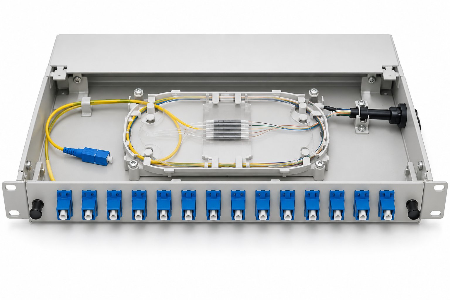
Pigtails deserve a specific note, because they are the piece most often under-stocked. When a restoration ends at an ODF or a panel, the crew terminates incoming fiber with factory-polished pigtails spliced onto the cable, and if the right pigtail type (connector, polish, fiber count, length) is not on the truck, the job stalls at the last step. For guidance on specifying them, see our article on what a fiber optic pigtail is and how to specify one, and our fiber optic pigtail product page, where you can review available connector types, fiber modes, and length options before adding spares to your inventory. Having pre-terminated pigtails on hand turns a mid-span break into a straightforward splice-and-restore task rather than a prolonged outage. Finally, no emergency kit is complete without a few spare patch cords. Keep at least two SC-SC single mode patch cords meeting the G.652D standard in the kit, as damaged or contaminated jumpers are among the most common causes of link loss during field repairs. You can order replacements through our SC-SC single mode G.652D patch cord page. All Nexora patch cords and pigtails are factory-tested and backed by a 12 months from shipment date warranty, so the spares you pack today will perform when you need them most.
How Do You Execute a Buried Cable Repair Step by Step?
A buried cable repair is a sequencing exercise. Each step depends on the one before it, and skipping one almost always costs you more time later in the day. The sequence below reflects what experienced restoration crews actually do on site, in order.
Step 1: Locate and mark. Before anyone touches a shovel, translate the OTDR fault distance into a physical position. Walk the route with the route drawings and a measuring wheel, allow for the difference between cable route length and ground distance (ducts detour, aerial spans cross roads, slack loops exist in handholes), and mark a working zone on the ground. Call the local utility locating service where it exists — striking a gas or power line while digging for a fiber fault turns a bad day into a dangerous one. Mark the zone wider than you think you need; fault distances from OTDR readings are typically accurate to within a few meters at best on long spans.
Step 2: Expose the cable with care. Excavate down to roughly 300–500 mm above the expected cable depth (typical direct-buried depth varies by region and contract — confirm the as-built drawings) using a machine, then switch to hand digging and vacuum excavation where available. Shovels are the classic cause of secondary damage: crews have opened a sheath fault and driven it into a full fiber break by prying at the cable. Expose enough cable on both sides of the visible damage to give yourself working room — usually at least 2–3 meters beyond the fault on each side as a practical field rule.
Step 3: Reconcile OTDR distance with physical markers. Once the cable is exposed, verify that this is actually the right fault. Measure the cable's printed length markings against your OTDR reading. If they do not agree within a few meters, you may be looking at a different defect — or the real fault may be further along, inside a duct where water ingress has been masking it. Cutting a cable you cannot re-join cleanly is an expensive mistake, so confirm before you cut.
Step 4: Cut out the damaged span. Remove the entire damaged section back to sound cable on both ends. A common field error is trying to conserve cable by splicing close to the visible damage, only to find crushed fibers or water-stained attenuation extending further than the sheath injury suggests. Cut back until the fiber ends you are splicing to are clean and dry. Plan for slack: each splice closure needs its stored slack, and you will need extra length at each end for re-stripping and splicing. A practical allowance is several meters of extra cable per closure beyond the minimum closure slack requirement — undershooting here forces a second splice or worse, a second closure.
Step 5: Install the replacement span. You have two standard topologies. If the damaged section sits between two existing closures, you can install one new closure at the fault location and run the replacement span between it and the nearer intact closure — but this only works if the surviving closure has spare capacity and the existing slack loops can reach. The cleaner and more common approach is two new closures: cut back to sound cable on both sides and splice a new replacement span between them. This gives you full control of both splice points and fresh slack storage on each side. For details on closure selection and slack storage geometry, our guide on choosing a splice closure and managing slack storage covers the layout rules in depth.
Step 6: Respect mechanical limits during handling. The replacement span is most vulnerable while you are paying it off the drum and routing it into position. Typical minimum bend radius for outdoor loose-tube cable is around 15–20 times the cable diameter during bending under load and lower at rest, and typical maximum pulling tension is in the range of a few kilonewtons depending on construction — confirm against the product datasheet before ordering and before pulling. Never drag cable over sharp trench edges, and never bend it tightly around a corner of the excavation to "just get it in". The contractor's guide to cable pulling tension and bend limits details the handling techniques that keep a new span healthy.
Step 7: Re-route if the duct is blocked. When the fault is inside a duct and the duct itself is collapsed, silted, or deformed, do not fight it. Sweeping the duct, measuring the obstruction, and deciding quickly between duct repair and a shallow re-route is a judgment call your crew lead should make within the first hour on site. A short surface-mounted or shallow-buried reroute with proper protection (conduit, warning tape, marker posts) is often faster and no less reliable than excavating a blocked duct segment under time pressure. For the underlying civil work, see the practical guide to trenching, ducts and backfill.
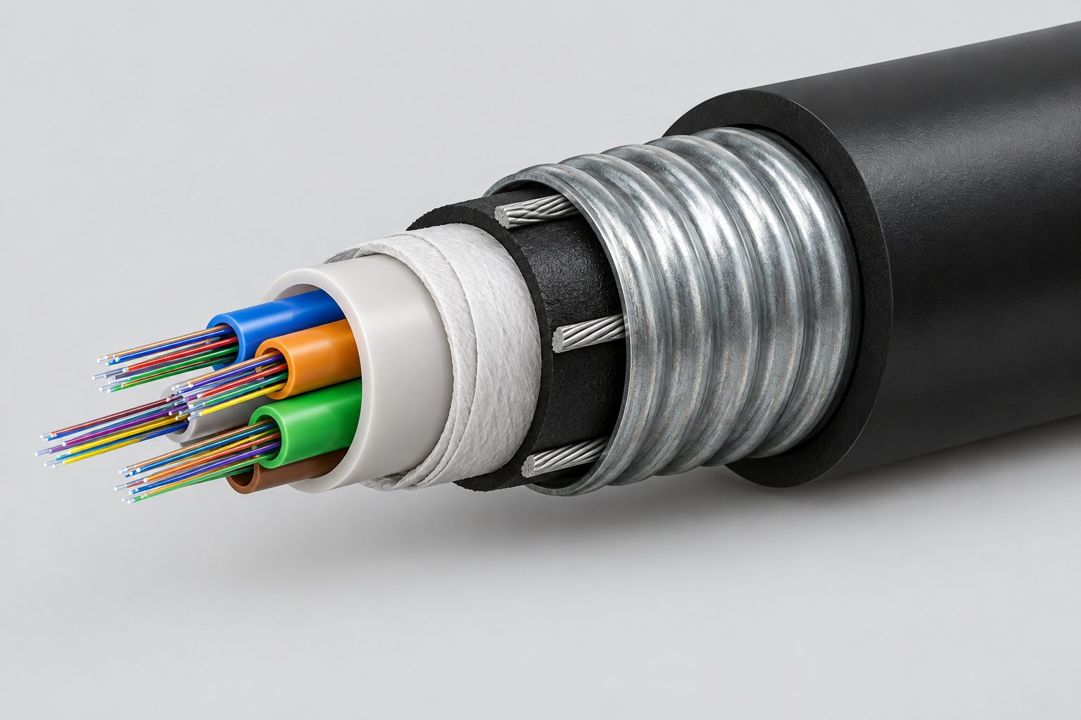
Matching the replacement cable. The replacement span should match the original in fiber type (G.652D is the standard single-mode fiber for most outdoor plant), fiber count, construction, and armor. Splicing G.652D to a different fiber class works optically in many cases but introduces mode-field mismatch loss and complicates your link budget records. Keep one matching drum per route where you can — our outdoor G.652D single-mode cable and armored cable ranges cover the constructions most commonly specified for buried routes, and both can be ordered in custom repair lengths rather than full standard reels.
How Do Aerial and Indoor Repairs Differ?
Buried repairs are about excavation and closures. Aerial and indoor repairs fail for different reasons and demand different skills, so a crew trained only on buried work will move slowly on poles and badly in risers.
Aerial restoration
Access is the first constraint. Bucket trucks are the default where the route is vehicle-accessible; ladders and climb belts are used where they are not, and each method carries its own safety regime. Never underestimate how much of an aerial repair schedule is set by access logistics, not splicing.
Construction type drives the repair method. On figure-8 self-supporting cable, the damage usually involves both the messenger and the optical unit, so the repair must restore mechanical tension on the steel messenger as well as optical continuity — typically with tension clamps or preformed grips on the messenger and a splice closure suspended independently so it carries no tensile load. Our guide on the figure-8 self-supporting cable explains the span mechanics you must respect. ADSS is the opposite case: the cable itself is the strength member, so the repair must re-establish the correct sag and re-secure tension and suspension clamps at the structure. If sag is wrong after a repair, the span either over-tensions in cold weather or violates clearance in wind — a defect that appears months later. See the ADSS-specific considerations in our ADSS aerial network guide.
Weather windows matter more than on buried work. Wind, lightning risk, and rain restrict bucket and climbing work, and a closure spliced in drizzle risks water ingress if the closure is not sealed meticulously. Build a weather buffer into your restoration SLA for aerial routes.
Indoor restoration
Indoor repairs are smaller physically but stricter procedurally. The governing constraint is fire code: replacement cable in plenum spaces, risers, or horizontal runs must match the fire rating the building was designed for. You cannot temporarily substitute an outdoor-rated cable indoors while you "sort the paperwork later" — most jurisdictions treat that as a compliance violation, not a repair shortcut. Our guide to riser, plenum and horizontal indoor cable selection sets out which rating applies where.
Handling differs too. Indoor tight-buffered cable has a stiffer buffered fiber (typically 900 µm) that tolerates direct connectorization without pigtails, which makes patch-level restoration fast — but the fibers are less forgiving of tight bends than loose-tube construction, and typical bend radius rules still apply (confirm the datasheet). Keep indoor drums in your repair kit stocked in the ratings you actually deploy.
Finally, decide the restoration level before you start. If the damage is confined to a patch cord or a short jumper at the panel, the fastest permanent fix is replacement with a new factory-terminated cord, not a field splice — keep SC/LC patch cords in the emergency kit for exactly this. If the damage is in the distribution cable itself, restore at the panel with pigtails and adapters so future moves, adds, and changes stay clean. Panel-level restoration also gives you a natural point to re-verify connector end faces, which is the single most common source of "the repair failed" callbacks.
How Do You Verify a Repair Before Closing the Ticket?
A repair is not finished when light goes through it. It is finished when you have measured it, documented it, and the numbers match your project specification. Every one of these steps should happen before the closure is finally sealed and the trench is backfilled or the bucket leaves the pole.
Clean and inspect every end face. Before any connector is mated and before every splice, the fiber end must be clean. Contamination is the leading cause of avoidable loss and of intermittent links that surface weeks later. Inspect with a scope, clean with proper one-click tools or lint-free wipes and solvent, and re-inspect — the discipline is cheap and the callback is not. The full procedure is in our guide on cleaning and inspecting fiber connectors.
Shoot the OTDR both ways. Measure through each new closure from both directions. Bidirectional measurement averages out the apparent loss anomaly that happens when two spliced fibers have slightly different backscatter characteristics — a splice can read artificially high from one end and artificially low (even a "gainer") from the other. Test at both 1310 nm and 1550 nm where possible, since water-affected or over-bent sections show up more clearly at 1550 nm.
Verify insertion loss against the budget. An end-to-end light source and power meter reading is the number your customer actually experiences, so record it. Compare it against the link loss budget you calculated at design time: the new splices and closures consumed some of your margin, and you need to know how much is left for the next incident. If you do not have a documented budget for that link, this is the moment to produce one.
Check connector polish and fiber mapping. While polarization is not a concern for standard single-mode data links, physical correctness absolutely is: mating a UPC connector into an APC adapter path gives high loss and permanent end-face damage, and it is a mistake made in a hurry during every major restoration. Know which polish each route uses before you reach for a patch cord — the differences are set out in our UPC vs APC guide. Equally important: verify fiber mapping through the new closures. After splicing, fibers are frequently re-ordered, and if your records do not match the physical plant, the next troubleshooting session starts with a false premise.
Acceptance values. As common field practice, a new fusion splice is typically accepted below roughly 0.1–0.3 dB, and a mated connector pair typically below 0.5 dB — but these are typical industry values, not guarantees. Always confirm acceptance thresholds against the project specification and the cable and component datasheets before you order and before you test; our guide to reading a cable datasheet shows which values to check.
Document the as-built changes. Record the new closure GPS coordinates, the fiber renumbering, the updated splice map, the replacement span's serial and reel numbers, and the insertion loss readings. Update your route records the same day, while the crew remembers the details. A perfect repair with wrong documentation will cost you more at the next fault than the repair itself did.
How Should You Prepare Documentation and Reserves Before the Next Incident?
The fastest restoration is the one where nothing has to be found out on the day. Everything below is preparation you can do in normal working hours.
Maintain as-built route drawings with depth and offset. As-built drawings should show the route, burial depth, duct occupancy, handhole and closure positions, and every deviation from the original design. Crews working from design drawings instead of as-builts routinely dig in the wrong place — a delay that dwarfs every other factor in a buried repair. Attach OTDR baseline traces to each route so fault distance readings have something to be compared against.
Keep closure and fiber numbering records current. Every closure should have an ID, a GPS fix, a date, a splice map, and a list of which fibers pass through and which are through-spliced versus dropped. Number fibers consistently and stick to it — a route where fiber 12 is fiber 12 at every closure is a route that gets restored quickly. If you are not confident your color-code discipline survives contact with multiple subcontractors, refresh the crew with our on-site color code guide.
Store spare drums properly. Spare cable that has been sitting outdoors for two years is not a spare; it is scrap with delamination risk and UV-degraded sheath. Store reels indoors, off the ground, on reel racks, away from sunlight and moisture, and rotate stock so the oldest drum gets consumed in planned work first. The storage practices that prevent damage and waste are detailed in our warehouse storage guide.
Audit the emergency kit on a schedule. Closure seals, splice protectors, cleaning supplies, and batteries have shelf lives and a habit of disappearing between incidents. A quarterly audit — checklist, open every case, replace what is missing — turns your emergency kit from a probability into a guarantee. Include a check that each route's designated spare drum still matches that route's current cable specification, since routes get re-cabled over the years.
Train and rehearse the crew. Run a restoration drill once or twice a year: a simulated fault, full OTDR location, dig or climb, splice, test, document. Crews that have rehearsed the sequence work at a fundamentally different speed than crews encountering it live. Rotate newer technicians through the drill so the knowledge does not sit with one senior splicer who might be on leave when the cable is cut.
When Is Full Cable Replacement the Better Decision?
Emergency splicing solves the incident in front of you. Sometimes the honest engineering answer is that the span is done, and patching it again would be paying labor to defer the real cost.
Multiple damage points on one span. If a rodent, a rock blast, or a construction crew has hit the same span in several places, splicing each point adds a closure and a set of splices at every location. Three or four closures in one span is a permanent reliability liability — every closure is a potential water ingress point and every splice a potential future fault. One clean replacement span is cheaper over the cable's life.
Water has traveled a long section. When water ingress has been running for months — common with an old closure or an unnoticed sheath breach — attenuation often degrades along a long stretch, not at a single point. OTDR traces that show a gradual slope change over hundreds of meters rather than a discrete event indicate cable whose water-blocking has failed along its length. Cut-and-splice at one point will not fix that; replace the affected section.
Repeated faults on the same route. A route that fails every rainy season, or in the same excavation-heavy corridor, is telling you something about its environment or its original installation. Replace it with the right construction — armored where rodents and rocks dominate, deeper or rerouted where diggers dominate — rather than re-splicing an annual ritual.
Aging cable near end of design life. Outdoor cables typically carry design lives measured in decades (commonly quoted around 20–25 years depending on environment and installation quality), but water exposure, thermal cycling, and installation damage shorten real life considerably. If your fault history shows a route trending toward frequent failures, plan a proactive replacement on your schedule instead of reacting on the cable's.
Planning the replacement. Existing routes usually have usable ducts, which makes replacement a pulling exercise rather than a civil exercise — survey duct condition first. Schedule a planned outage window with customer notice rather than restoring under emergency conditions. When procuring the replacement, write a complete RFQ covering construction, fiber count, armor, length per drum, packing, and test documentation; our guide on what to include in a cable RFQ gives you the checklist. On delivery, inspect every reel before it goes into storage — sheath condition, drum integrity, labels, and factory test sheets — per the export packing and delivery inspection guide. A replacement reel that arrives damaged and gets stored anyway is next year's emergency.
How Can Your Cable Supplier Shorten Your Restoration Cycle?
Your restoration speed is bounded by two things: your own preparation, and how fast you can get the right cable when the spare drum is not enough. The second factor is contractual, and you can fix it before any incident happens.
Agree matching constructions in advance. Give your supplier the exact constructions deployed on each route — fiber type, count, armor, sheath material, drum lengths — so a replacement order is a reference, not a re-specification exercise done under pressure. A manufacturer who already knows your plant can quote and confirm same-day.
Arrange custom lengths. Repair spans rarely match standard reel lengths, and ordering a full standard drum for a 600-meter repair wastes budget and warehouse space. Agree upfront that repair quantities can be cut to custom lengths, and confirm the manufacturer's MOQ for such orders — many are more flexible on repair quantities than on production orders, but only if you ask first.
Establish an emergency order channel. Know who to contact, what information speeds the order (route spec, length, deadline, delivery address, packing preference), and what the realistic lead time is for urgent production. Our article on MOQ and lead time when ordering from a manufacturer explains what to expect and what to negotiate. A supplier with genuine OEM/ODM capability can also match non-standard constructions you inherited from previous vendors — see how Nexora supports OEM/ODM fiber optic projects.
Check documentation quality before you need it. A supplier whose datasheets are complete, whose reel labels carry fiber count, length, and build date, and whose color coding follows recognized practice is a supplier whose product your crews can work with at 2 a.m. Documentation quality correlates strongly with factory discipline — audit it when things are calm.
Understand the warranty terms. Nexora's warranty is 12 months from shipment date; know what that covers and what it does not so that a warranty claim never slows a restoration. Our guide on what a 12-month warranty covers sets out the practical boundaries for buyers.
Frequently Asked Questions
How long does a typical field restoration take?
As typical industry experience: a simple buried sheath fault with good access and an available crew is often restored within 4–8 hours from arrival. A fault requiring excavation, two new closures, and a replacement span commonly runs 8–24 hours. Aerial work depends heavily on access and weather, and multi-span damage can take several days. These are indicative figures only — actual times vary with route conditions, crew size, and permitting.
Can a damaged cable be repaired without shutting down other fibers in the cable?
Usually yes. In a loose-tube cable, the damaged fibers can often be accessed and spliced while adjacent tubes and fibers remain live, provided the fiber being worked on is dark and crews avoid disturbing live fibers' slack. However, cutting the cable open introduces vibration and bend risk to neighboring fibers, so for critical routes many operators prefer a brief maintenance window. Assess the physical condition of the cable first — if water or crushing has affected multiple tubes, a full span replacement with an outage is the safer plan.
How much new cable should be inserted at a repair point?
Practically, insert enough to cover the removed damaged section plus closure slack storage at each end, plus working length for stripping and splicing — a common field allowance is roughly 15–30 meters total for a two-closure buried repair, but the exact figure depends on the closure model's storage tray capacity and your organization's slack loop standards. Confirm against the closure datasheet and your own engineering practice; do not trim to the minimum, because the next fault may be nearby and slack is your friend.
Does a repaired section perform as well as the original cable?
Optically, a properly executed fusion splice typically adds well under 0.1–0.3 dB per splice, so a single repair is usually indistinguishable in service from the original link — as typical values, always confirmed against your project specification. The differences are structural, not optical: new closures are potential water ingress points, and the splice count is permanently higher. That is why verification testing and accurate records matter as much as the splice quality itself.
Should we keep one spare drum per route?
Ideally yes for critical routes: one drum per route, matched in construction and fiber count, stored indoors on racks and rotated through planned work so it does not age in storage. For long networks this gets expensive, so a common compromise is one shared spare per cable type in your plant, sized for the largest typical repair span, plus a standing agreement with your supplier for fast custom-length production. The economics improve further if the spare drum is consumed in routine projects and reordered before it runs out.
What information speeds up an emergency order?
Five things: the exact cable specification (construction, fiber type, count, armor, sheath), the length needed per drum and number of drums, the required delivery date, the delivery address and receiving contact, and any packing preference. Send it in writing even if you also call. Suppliers can move fastest when they do not have to guess, and a pre-agreed template — which Nexora can set up with you in advance — turns the ordering step from an hour into minutes.
Key Takeaways for Fiber Optic Network Operators
- Sequence buried repairs: locate and mark, expose by hand near the fault, reconcile OTDR distance with physical markers, then cut back to sound cable before splicing — never splice close to visible damage.
- Match the replacement span to the original construction and fiber type, and respect typical bend radius and pulling tension limits during handling — confirm values against the datasheet.
- Aerial and indoor repairs follow different rulebooks: restore messenger tension and sag on figure-8 and ADSS spans; match fire ratings indoors and prefer panel-level restoration.
- A repair is complete only after bidirectional OTDR testing, insertion loss verification against the link budget, connector cleaning and inspection, and same-day as-built documentation.
- Preparedness beats speed: current as-builts, indoor-stored spare drums, audited emergency kits, and rehearsed crews shorten every future restoration.
- Know when to stop splicing — repeated faults, water-damaged lengths, and multiple damage points justify full span replacement on your schedule rather than the cable's.
Emergency performance is largely decided before the incident. If you are reviewing your repair stock, planning replacement spans, or want a supplier who can hold matching constructions and produce custom repair lengths quickly, talk to Nexora. As a Shenzhen-based manufacturer of outdoor G.652D, armored, ADSS, figure-8, and indoor cables, patch cords, adapters, and pigtails, we support OEM/ODM customization and emergency order handling for network operators and contractors. Our warranty is 12 months from shipment date, and all performance values referenced in this article are typical industry figures — always confirm against the relevant product datasheets before ordering. Contact our team to build your restoration stock plan.