
A practical B2B guide to installing direct-buried fiber optic cable: choosing between direct burial and duct, burial depth, trenching and bedding, pulling cable into ducts, backfill and warning tape, slack and splice planning, and pre-backfill OTDR testing.
Every fiber optic network has a moment when the cable stops being a product and becomes an engineering decision. For underground routes, that moment usually arrives when the buyer realizes the cable itself is one of the cheaper line items on the quote. Trenching, ducting, bedding, backfill, and restoration routinely cost several times the price of the cable, and once the soil goes back in, nobody can inspect the work without digging it up again. That is why direct-buried installations reward careful planning more than almost any other cabling method: the mistakes are literally buried.
This guide is written for the people who actually make those decisions on B2B projects: network owners, contractors, ISPs, and procurement teams specifying cable for campus backbones, rural FTTH feeders, CCTV and SCADA backhaul, and industrial sites. It walks through the full sequence — choosing between direct burial and duct, selecting a cable construction that survives underground, setting burial depth, preparing the trench, pulling cable into ducts, backfilling correctly, planning slack and splice points, and testing before acceptance. Wherever a number appears in this article, treat it as typical industry practice, not a guarantee; the governing values are always the cable datasheet, the project specification, and local regulations.
What "Direct-Buried" Actually Means (and When It Is the Right Choice)
"Direct burial" describes an installation method, not a cable type. It means the cable is placed into the ground itself — at the bottom of a trench, in a plowed furrow, or through a bore — without being enclosed in a separate protective conduit along the entire route. The cable's own jacket and armor are the primary protection against soil, moisture, rodents, and mechanical stress. This is different from a ducted installation, where the cable sits inside HDPE or PVC pipe, or an aerial installation, where it hangs from poles. Many real projects combine all three methods on one route, and recognizing where each belongs is the first planning decision.
Direct burial earns its place on routes where the ground will not be disturbed for a long time and where the cost of duct would buy little benefit. Typical examples include inter-building links on factories, campuses, solar farms, ports, and mining sites; rural feeder segments between villages in FTTH rollouts; long runs between roadside cabinets; and connections to remote equipment such as water pumping stations, cell site backhaul, or perimeter surveillance systems. On these routes the civil works dominate the budget, and any structure that adds installation steps without adding protection value is a cost with no return.
Direct burial is usually the wrong choice where the route crosses active construction zones, where the ground is expected to be re-opened frequently, where the soil is aggressively corrosive or unstable, or where the network owner plans significant future capacity upgrades. In those situations, duct costs more on day one but repays itself the first time a cable must be replaced or upgraded without re-excavation. A practical rule many project teams follow: bury directly across stable open ground, and place duct wherever the route crosses a road, railway, driveway, irrigation canal, or any section that may be re-opened for other utilities within the network's design life.
One more distinction matters at specification time. A cable can be suitable for direct burial without being optimized for it. Any outdoor loose-tube cable with a moisture barrier can technically sit in soil, but a cable designed for direct burial adds armor, heavier sheathing, and rodent protection because it will rely on its own structure for decades. Conversely, a cable designed for duct pulling may be lighter and lower-friction but will not survive sharp stones in compacted backfill. Specifying the wrong one either wastes money or shortens the route's life.
Direct Burial or Duct: Which Installation Method Fits Your Route?
The choice between direct burial and duct is not a pure engineering question; it is a trade-off between first cost, future flexibility, and risk tolerance. The table below summarizes how the two methods compare on the factors that usually decide the outcome.
| Factor | Direct burial (cable in soil) | Duct installation (cable in pipe) |
|---|---|---|
| Civil works cost | Lower. One operation: open trench, lay cable, backfill. | Higher. Trench plus duct laying, jointing, and end sealing. |
| Installation speed | Fast on open ground, especially with plowing. | Slower; duct must be laid, cleaned, and capped before pulling. |
| Protection level | Depends entirely on cable construction and workmanship. | Physical barrier; better in rocky, corrosive, or high-traffic soil. |
| Future upgrade or repair | Repair means re-excavation; upgrade means a new route. | Cable can be pulled and replaced without re-opening the trench. |
| Rodent and termite risk | Requires armored cable in risk zones. | Duct itself deters most rodent damage. |
| Best suited to | Stable rural routes, campuses, long straight runs. | Urban routes, road crossings, sections expected to change. |
Two practical observations from underground projects help buyers decide. First, the labor market matters more than the materials. In regions where skilled civil crews are cheap and cable splicers are scarce, teams tend to favor fewer, longer direct-buried sections and concentrate splicing at planned points. Where labor is expensive and equipment rental is easy, the equation shifts toward duct because machines do more of the work. Second, ownership of the route matters. If the network owner controls the whole corridor for its design life, direct burial is a reasonable bet. If other utilities, road authorities, or developers may dig in the corridor at any time, duct — or at least ducted crossings — is cheap insurance.
A hybrid layout is the default answer for most projects: direct-bury the long stable segments, duct the crossings and urban sections, and place accessible transition points (handholes or small manholes) where the method changes. When you request quotations, describe the route in exactly these segments rather than as one "underground route". Suppliers and installation contractors price a segmented route far more accurately, and the drawing you receive back will show splice points and slack locations that match reality instead of assumptions.
Which Cable Construction Survives Underground?
Underground cable fails for three reasons: water eventually finds a way in, something crushes or cuts the structure, and rodents chew whatever they can reach. A direct-burial cable design answers each of these with specific construction choices, and buyers who understand those choices can read a datasheet in minutes instead of trusting a sales line.
Core and buffer tube
Nearly all outdoor underground routes run single mode fiber, most commonly G.652D for standard links, with bend-insensitive G.657A2 used where tight routing is expected at splice closures or building entries. The fibers sit inside gel-filled or dry water-blocking loose tubes, which isolate them from mechanical movement in the cable. Typical attenuation values for G.652D fiber are around 0.35 dB/km at 1310 nm and 0.21 dB/km at 1550 nm, and typical operating temperature range is roughly -40 °C to +70 °C — but these are typical values only; the datasheet of the cable you actually order governs. Fiber count is a network planning decision rather than an installation one; if you are still deciding, see our guide on choosing the right fiber count.
Water blocking
Underground cable will get wet eventually, so the design question is not "if water enters" but "how far it can travel when it does". Water-blocking options include gel-filled tubes, dry superabsorbent yarns and tapes, and a combination of both. Dry-core designs are increasingly preferred because they splice faster and cleaner — no gel to wipe off — and they are easier for crews who handle fiber occasionally rather than daily. Either approach works when it is properly applied; what matters is that water blocking is continuous through the core, around the central strength member, and under the armor.
Armor and jacket
This is where direct-burial cables earn their price difference. Common armor options are:
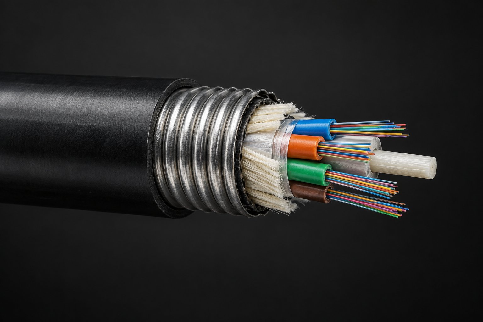
- Steel tape armor (STA): a corrugated or longitudinal steel tape, often plastified or laminated, that provides strong crush resistance and a complete moisture barrier. It is the standard choice for most direct-burial routes.
- Steel wire armor (SWA): round steel wires helically wound around the core, adding tensile strength for pulling into ducts and protection in rockier or deeper installations.
- Corrugated steel tape with PE outer sheath: the widely used configuration for buried telecom cable, combining flexibility with rodent resistance.
- Non-armored: acceptable inside continuous duct in protected environments, but not recommended in direct soil contact.
The outer sheath is normally black HDPE or MDPE for UV and soil resistance; low-smoke zero-halogen compounds belong indoors, not underground. In rodent-heavy regions — farmland, plantations, some coastal areas — armor is not optional, because unarmored cable in soil is a documented attractant for rodents seeking dental wear. Our armored cable buyer's guide covers the selection logic in detail, and the Armored Fiber Optic Cable product page shows the constructions available.
What "typical" means when you compare datasheets
When two suppliers quote cables with similar names, compare four things line by line: armor type and thickness, sheath material and diameter, water-blocking method, and the rated crush and tensile performance. Crush resistance and maximum pulling tension are the two numbers most often presented with different test methods, so ask under which standard and condition each figure was measured before ranking offers. Any performance figure in this article — depth, bend radius, tension, temperature — is industry-typical guidance; the values printed on the datasheet of the cable you order always govern.
How Deep Should Fiber Optic Cable Be Buried?
Burial depth is where local practice, soil, and regulation intersect, and it is the specification most often copied from the last project without checking. The depth that matters is not the average depth along the route; it is the minimum depth at the worst point, because that is where the backhoe, the plow tine, or the drainage ditch will eventually meet the cable. The table below collects typical practice ranges used across many markets. They are typical references, not legal requirements — the depths mandated by local authorities, landowners, and the project specification always take precedence.
| Route context | Typical burial depth | Notes |
|---|---|---|
| Landscaped areas, sidewalks, greenfield rural land | 0.6 – 0.8 m | Minimum depth for protection against common gardening and agricultural activity. |
| Road verges and areas subject to vehicle loads | 0.8 – 1.2 m | Deeper where heavy vehicles routinely pass over the route. |
| Under roads, driveways and crossings (in duct or bore) | 1.0 – 1.5 m | Usually placed in duct or protective pipe; depth per road authority requirements. |
| Agricultural land with deep plowing | 1.0 – 1.2 m | Confirm plowing depth with the landowner; mark the route clearly. |
| Frost-susceptible regions | Below local frost line | Frost heave moves shallow cable; depth follows local building practice. |
| Rocky terrain where deep excavation is impractical | Shallower with cover | Use duct plus concrete cover or cable protection tiles per design. |
Three factors push depth beyond the minimum. First, freeze depth: in cold climates, cable laid above the frost line moves with the soil each winter, which fatigues splices and closures even when the cable itself survives. Second, future excavation: if the corridor may be re-opened by other utilities, extra depth is cheaper than a damaged route. Third, separation from other services: maintain a practical horizontal and vertical separation from power cables, gas lines, and water mains — commonly on the order of 0.3 to 0.5 m from other utilities, or whatever the local utility coordination rules require. Power separation is not just a damage question; it also simplifies locating and future maintenance work.
Depth consistency is a workmanship issue as much as a design one. Trench depth varies naturally with soil, and crews cutting through hard material are tempted to ride shallow. Walking the trench before laying and spot-checking depth — especially at road crossings, drainage ditches, and field entrances — is the cheapest insurance in the entire project. Where the route is plowed rather than trenched, verify that the plow maintains depth under changing soil resistance; a plow that rises over a rock leaves a shallow arc of cable exactly where stones are most numerous.
Planning the Route: Survey, Utility Locates, and Permits
Underground work punishes optimism. The planning phase costs a fraction of the civil works, yet it decides whether installation runs in days or stalls for weeks. A realistic planning sequence looks like this:
- Walk and map the route. Record every crossing — roads, drives, fences, culverts, irrigation lines, drainage ditches — and every point where the installation method changes. Each crossing is either a bore, a duct, or a scheduled splice point, and each one needs a decision before equipment arrives.
- Locate existing utilities. In most markets a "call before you dig" service is legally required; where it is not, contract a utility survey. Striking a power or gas line is a safety incident first and a cost incident second, and it stops the project on the spot.
- Check soil and obstacles. Rocky soil changes the tools, the depth strategy, and the cable specification. Waterlogged or corrosive soil may push the design toward duct or special sheathing. A few trial holes along the route are cheaper than discovering rock at meter 400 of a 2 km trench.
- Secure permits and right-of-way. Road authorities, railways, and private landowners each have their own approval timelines. Permits are the most common source of schedule slip on underground projects, and they are almost never compressible at the end.
- Plan drum lengths and splice points. Cable arrives on reels in fixed lengths — commonly 2 to 5 km per drum for outdoor cable, subject to the supplier's standard packing. Match drum length to the distance between planned splice points so that mid-route splices happen where you chose to put them, not where the drum ran out. Our MOQ and lead time guide explains how drum lengths and reel sizes are typically quoted.
- Plan delivery and handling. Multi-kilometer reels weigh hundreds of kilograms and need delivery access, lifting equipment, and paying-off stands positioned where the pull starts. Reels rolled off a truck and dropped on their flange can be damaged before the first meter is laid.
Document the plan as a route drawing with station numbering. Every later step — depth checks, splice records, OTDR traces, future fault location — refers back to those station numbers, and the drawing becomes the first page of the as-built documentation you will want at handoff.
Trenching and Bedding: Getting the Bottom Right
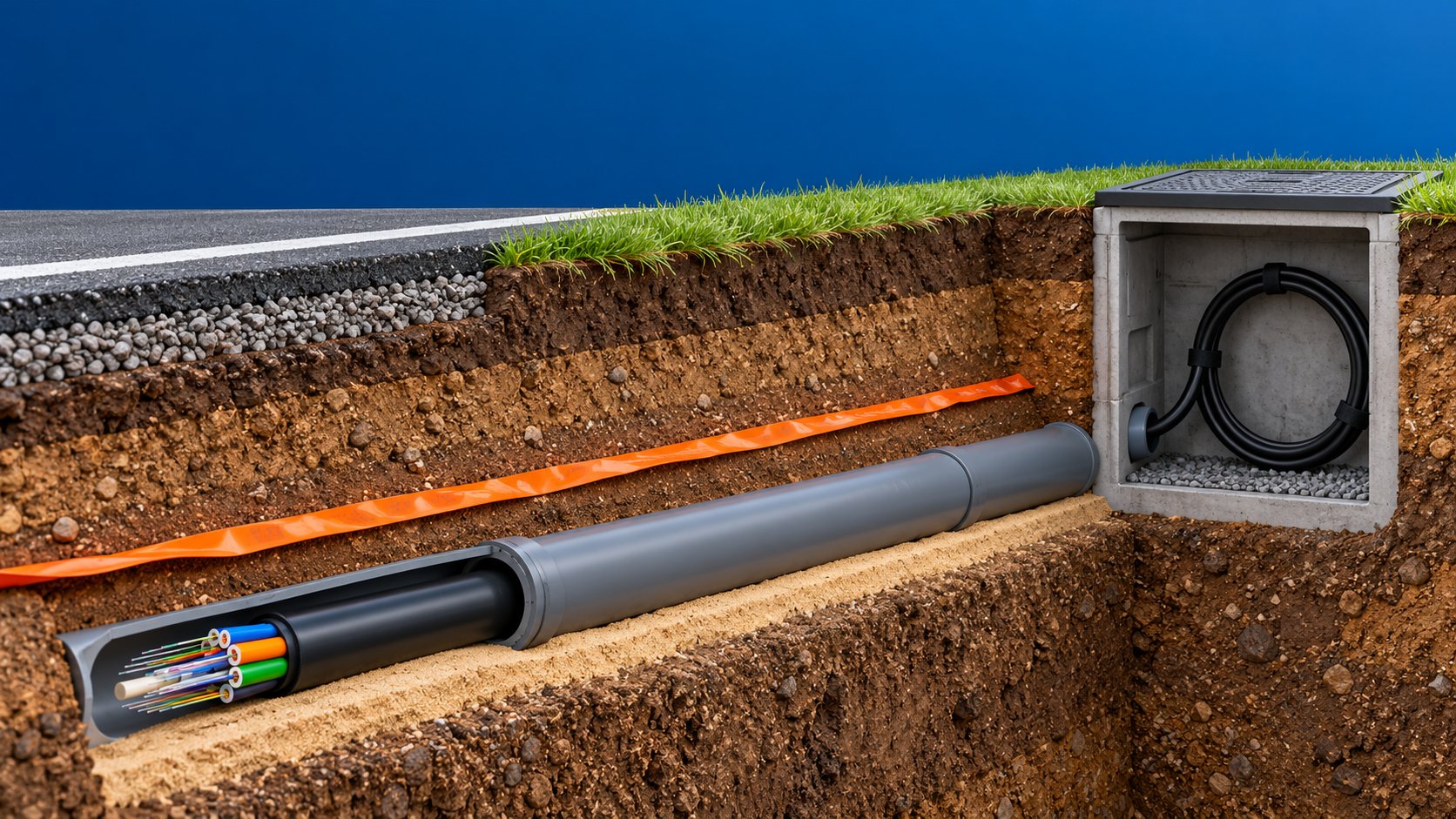
Most cable damage attributed to "bad backfill" actually starts at the trench bottom. Soil directly under the cable compacts under load; any stone left proud of the bottom becomes a point load pressing into the sheath year after year. The fix is inexpensive and well understood: excavate to full depth, then add a bedding layer of sand or fine selected material — typically 75 to 100 mm compacted, a common industry practice rather than a fixed rule — and rake it smooth before the cable is laid. On rocky routes, the bedding layer does double duty: it is the only thing standing between the sheath and the edges of the rock that the excavator inevitably leaves behind.
Trench width is a cost lever worth understanding. Wider trenches are safer and easier to work in, but they move more soil and cost more to restore. Narrow, machine-cut trenches (50 to 300 mm in some plowing and micro-trenching applications) install quickly in stable soil but leave little room for workmanship — the cable has nowhere to go except exactly where the blade put it. Conventional open trenching, typically 300 to 600 mm wide for a single cable route, remains the default where depth is significant or the ground is mixed. Match the method to the soil and the route length, not to whichever machine happens to be available.
Bend radius deserves explicit attention at every corner and every vertical offset. Loose-tube outdoor cable tolerates bending far better than older designs, but the limit is still real: typical practice keeps dynamic bends (during pulling and laying) around 20 times the cable outer diameter and static bends (after installation) around 10 to 15 times the diameter, with the datasheet value governing. In practice this means hand-forming gentle curves at corners instead of dragging the cable around a sharp trench angle, and leaving slack at every direction change so the cable never takes a set. A cable that is kinked during installation may pass an OTDR test on day one and still fail two winters later, because the glass was stressed in a way the initial measurement did not reveal.
Road and stream crossings are the sections most worth doing well. Where open-cut is not permitted, horizontal directional drilling (HDD) or moling places a bore under the obstacle, and the cable — usually inside a duct — is pulled or pushed through afterward. Bore paths are engineered products: entry and exit angles, depth under the obstacle, and drilling fluid management all affect whether the crossing survives. Treat crossings as separately specified work packages with their own acceptance checks, because they concentrate the highest loads and the least accessibility of anywhere on the route.
Pulling Cable Into Ducts Without Damaging It
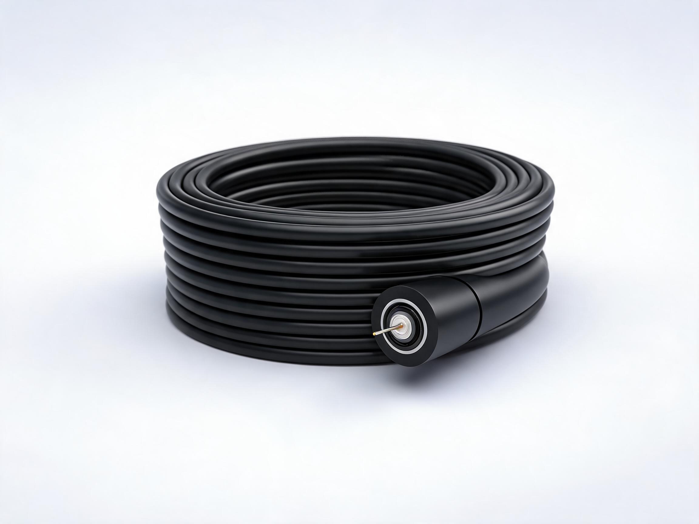
On hybrid routes — and on any ducted section — installation quality lives or dies in the pulling operation. The physics is simple: tension builds along the run with friction, weight, and every bend, and the cable's tolerance to that tension is finite and printed on the datasheet. Exceeding it stretches the cable, and a stretched loose-tube cable can show attenuated or broken fibers only after the pulling eyes are removed and the cable has settled.
Practices that consistently produce clean pulls:
- Match the cable to the duct. One cable per duct is the common default; sizing a duct for "someday more cables" usually produces an oversized, under-used bore and a cable that snags on its own slack. Typical duct utilization for a single cable keeps the cross-sectional fill well below half, per project specification. Our Outdoor G.652D Single Mode Fiber Optic Cable page lists typical outer diameters to check against your duct size.
- Clean and prove the duct first. Pull a mandrel and a brush through every duct section before cable day. Silt, sand, and a forgotten coupling left in a duct are the classic causes of a stalled pull.
- Use lubricant and steady speed. Friction drops dramatically with proper cable lubricant, and a steady pulling speed keeps tension predictable. Stop-start jerking loads the cable in impulses, which is exactly how rated tension gets exceeded on a run that "should have" been fine.
- Watch the tension, not the schedule. For runs long enough that calculated tension approaches the cable's limit, plan a mid-point assist or pull from the center out to both ends in a figure-8 pattern laid on the ground. The cable should be figure-8'd cleanly — flat crossings, no kinks — whenever it is taken off the reel and reloaded.
- Protect the ends. Every open cable end during pulling is an entry point for water and grit. Keep end caps on until the moment of splicing.
Pulling tension planning is a calculation, not a guess: run length, duct size, coefficient of friction, cable weight, and the number and angle of bends all enter it. Installation contractors normally run this calculation per duct section; network owners who receive it as part of the method statement gain a useful check on whether the crew has actually looked at the route. This article keeps the mechanics at planning level — if your project needs section-by-section tension engineering, that belongs in the method statement agreed with your installer and the cable supplier.
Backfill, Warning Tape, and Surface Restoration
Backfill is where the route is closed — literally — and where the difference between a 30-year installation and a 5-year one is decided by a wheelbarrow. The principles are few and old:
- Fine material first. Cover the cable (or duct) with 200 to 300 mm of fine, stone-free material — sand or selected fines — placed by hand and compacted lightly. This is the layer that actually protects the sheath; everything above it is only bulk.
- Compact in layers. Return the remaining spoil in lifts, compacting each before the next, until the trench is closed. Uncomplicated backfill settles, and a settling trench drags the cable down with it or leaves a depression that channels water along the route.
- Lay warning tape. A continuous colored warning tape (orange or red in most markets, printed "Caution: Fiber Optic Cable" or the local equivalent) goes roughly 300 to 450 mm above the cable, per local convention and project spec. It does not protect the cable mechanically; it protects it from the excavator operator who — years later — sees the tape and stops. In non-metallic installations, a locate tracer wire laid alongside gives future crews a way to find the route.
- Mark at the surface. Marker posts or tiles at direction changes, splice points, and regular intervals keep the route findable. Combined with accurate as-built drawings, they are the difference between a two-hour fault location and a two-day excavation.
- Restore the surface properly. Reinstatement of road verges, farmland, and sidewalks is usually a contractual requirement with its own inspection. Budget for it honestly: it is part of the cost of underground routing, not an optional extra.
One caution worth writing down: never backfill before the section has passed its pre-acceptance tests and the splice records are photographed and filed. Re-opening a trench to fix a documentation gap costs a full civil-works day and undoes every restoration already completed.
Splice Points, Slack Loops, and Access Chambers
Underground networks are planned around their splice points, because those are the places where future work will happen. At each splice location — a handhole, a pedestal, a small vault, or a joint directly buried in a splice closure — the design should provide three things: enough slack cable to bring both sides together and work on them, physical protection for the closure, and access without major excavation.
Typical slack provisioning runs at about 1 to 2 percent of route length overall, concentrated at splice points and method transitions, with coils of roughly 15 to 20 m left at each closure location in many projects — typical figures; the route design governs. Slack is not waste. It is what allows a splice to be re-made years later without pulling new cable, and what absorbs small ground movements over the route's life. Slack coils live in handholes, on racks inside closures' storage baskets, or in figure-8 loops in chambers — never buried in the backfill where they will be cut by the next shovel.
At the splice itself, each loose-tube fiber is typically prepared with a fiber optic pigtail — a short length of cable with a factory-polished connector on one end and fusion-spliced bare fiber on the other — so the connectorized side plugs into the closure's adapter panel while the splice is protected inside a heat-shrink sleeve. Factory-terminated pigtails move the precision-polishing work into a clean production environment, which is why most underground closures you open will contain pigtails rather than field-polished connectors. Planning the pigtail types (SC, LC, FC; UPC or APC) at design time avoids the classic field delay of splicing finished cable to pigtails nobody ordered.
Access chamber spacing balances cost against future convenience. Handholes every few hundred meters on urban routes; fewer, larger chambers on rural routes; direct-buried closures where even that is uneconomic. Whatever the interval, the chamber must drain, support the loads over it, and be large enough to work in — a chamber too small to loop cable in is a chamber that will be rebuilt during the first repair.
Testing Before You Backfill (and Before You Accept)
Underground testing has one non-negotiable rule: test every section before it is buried. An OTDR trace taken after the cable is laid but before backfill is the only baseline that reflects the installed route rather than the factory drum. If a fiber is damaged during laying, finding it now costs a re-lay of one section; finding it after backfill costs an excavation, a splice, and a re-test on a route that has already been "closed".
A practical pre-backfill test sequence for each section:
- Visual and mechanical check: cable ends intact, end caps on, no visible kinks or armor damage along the section, slack coils formed and secured.
- Continuity and identification: confirm fiber numbering and color-code sequence from end to end before any splicing begins.
- Bidirectional OTDR traces: test at 1310 nm and 1550 nm (and 1625 nm where used for monitoring), from both ends, and file the traces against station numbers. Our guide on using an OTDR for installation acceptance covers event analysis and acceptance criteria in depth.
- Insertion loss on link-level measurements where the project specification requires them, against the loss budget calculated at design stage — see how to calculate a fiber optic link loss budget.
- Documentation: splice schedules, OTDR files, depth check records, and photos of the open trench at representative points. This package is the as-built baseline.
Acceptance at handoff repeats the OTDR test against the pre-backfill baseline. Comparing the two traces is what turns "the cable was fine when it went in the ground" from an assertion into a record. Networks that skip the baseline almost always lose the argument about when damage occurred — and with it, the ability to separate workmanship issues from later third-party damage.
Specifying Cable for a Direct-Burial Project: A Buyer's Checklist
Underground cable is quoted against a specification, and vague specifications produce vague offers. The checklist below is the minimum information set that lets a manufacturer quote accurately — and it doubles as the comparison sheet for evaluating offers.
| Item | What to specify | Why it matters underground |
|---|---|---|
| Fiber type and count | G.652D or G.657A2; fiber count with spare pairs stated | Determines loss performance and future capacity; see our fiber count guide. |
| Construction | Loose tube; dry or gel water blocking; number of tubes | Water blocking governs long-term reliability; tube count affects splicing time. |
| Armor | Steel tape / steel wire / corrugated STA; or non-armored for duct-only | Crush and rodent protection; the core direct-burial decision. |
| Outer sheath | HDPE/MDPE; nominal outer diameter | Soil and UV resistance; diameter drives duct sizing and bend radius. |
| Performance | Attenuation, crush, tensile — quoted per datasheet, not as generic guarantees | Lets you compare offers on measured, documented values. |
| Environment | Operating temperature range; rodent/termite risk zone confirmation | Prevents an indoor-grade or duct-grade cable being quoted for soil. |
| Delivery | Drum length, reel type, drum packing, printing requirements | Drum length defines splice point spacing and pull planning. |
| Commercial | MOQ, lead time, warranty terms | Warranty for Nexora products is 12 months from shipment date; confirm terms in the order. |
When you send this to a supplier — our RFQ content guide lists the full set — ask explicitly for the datasheet of the exact construction being offered, and for the test standard used for crush and tension figures. Manufacturers with real production control answer both without hesitation. If your route includes aerial segments as well, compare the underground sections against aerial options such as ADSS — our article on when ADSS is the right choice for aerial networks helps decide where the boundary lies.
Seven Mistakes That Shorten an Underground Cable's Life
| Mistake | What it causes | What to do instead |
|---|---|---|
| Bending tighter than the datasheet radius at corners | Stressed glass that passes initial tests and fails later | Hand-form curves; leave slack at every direction change. |
| Backfilling with stones directly on the cable | Point loads that crush the sheath over seasons | Fine-material cover layer first; remove rock from contact zone. |
| Skipping warning tape and markers | Third-party excavation damage — the top killer of buried cable | Continuous tape 300–450 mm above; posts at intervals and direction changes. |
| No slack at splice points | Every future repair needs new cable and new civil works | Plan 1–2% slack, coiled at accessible closures. |
| Using duct-grade or indoor-grade cable in soil | Moisture ingress and rodent damage within a few years | Specify armored construction for direct-burial segments. |
| Pulling beyond rated tension to "finish the run" | Stretched cable; fiber breakage appearing days later | Calculate tension per section; use mid-assist or pull from center. |
| Backfilling before OTDR baselines are recorded | No evidence of when damage occurred; disputes cannot be resolved | Test and document every section before closing the trench. |
None of these are exotic errors; all of them are schedule-pressure errors. The projects that avoid them share a habit: the cable specification, the method statement, and the acceptance test plan are agreed before the excavator arrives, and the test plan has the authority to stop backfill.
Frequently Asked Questions
Can I bury regular outdoor fiber optic cable without armor?
Only where the cable sits inside continuous duct or another protective pipe. In direct soil contact, non-armored cable has no defense against stones, rodents, or future excavation, and most manufacturers will tell you so. If the route is genuinely ducted end to end, non-armored construction is a legitimate cost saving; if any segment touches soil, specify armor.
Is it cheaper to direct-bury or to install duct?
Direct burial is cheaper on day one — typically one civil operation instead of two — which is why it dominates rural and campus routes. Duct costs more upfront but makes any future cable replacement a pulling job instead of an excavation. The break-even depends on how likely your route is to be disturbed; for road crossings and urban sections, duct is almost always justified.
How deep do I need to bury the cable under a road?
Typical practice is 1.0 to 1.5 m under roads, usually inside duct or a protective bore, but the road authority's requirement governs. Treat crossings as separately engineered sections with their own depth, protection, and acceptance checks.
How much slack should I leave for future splices?
A common planning figure is 1 to 2 percent of route length overall, concentrated at splice points, with coils of roughly 15 to 20 m at each closure. The exact figures depend on your maintenance strategy — more slack costs little at installation and saves re-excavation later.
What warranty applies to direct-burial cable?
Nexora products carry a warranty of 12 months from the shipment date. Since buried infrastructure lives far longer than any warranty period, the real protection is correct specification and documented installation — which is why the datasheet, the method statement, and the pre-backfill test records matter more than the warranty clause itself.
Do I need to test cable that arrives on the reel?
Yes — a receiving check against the factory test report confirms the cable survived transport, and it takes minutes per drum. Then test again after laying, before backfill, and at final acceptance. Each trace has a different job, and the set of them is your quality record for the route's life.
Plan Your Underground Route With Real Cable Data
Direct-buried fiber routes reward the teams that decide cable construction, depth, slack, and test points as one design — not as four separate purchases. If you are specifying an underground segment now, the fastest next step is to send the route description (lengths, crossings, soil type, rodent risk) together with the checklist above, and ask for the datasheet of the proposed construction before committing.
- Browse the Armored Fiber Optic Cable and Outdoor G.652D Single Mode Fiber Optic Cable product pages for constructions and typical specifications, and Fiber Optic Pigtails for splice-point planning.
- For the selection logic behind armored designs, read When Should You Use Armored Fiber Optic Cable?
- For acceptance testing, see How Do You Use an OTDR to Accept a New Fiber Optic Cable Installation? and How Do You Calculate a Fiber Optic Link Loss Budget?
Every underground project ends with the same question — not "how fast did we install it" but "will it still be quiet in ten years". Cable that is correctly specified for the soil, laid at true depth on proper bedding, pulled within its limits, and documented before the trench closes answers that question with data instead of hope.