
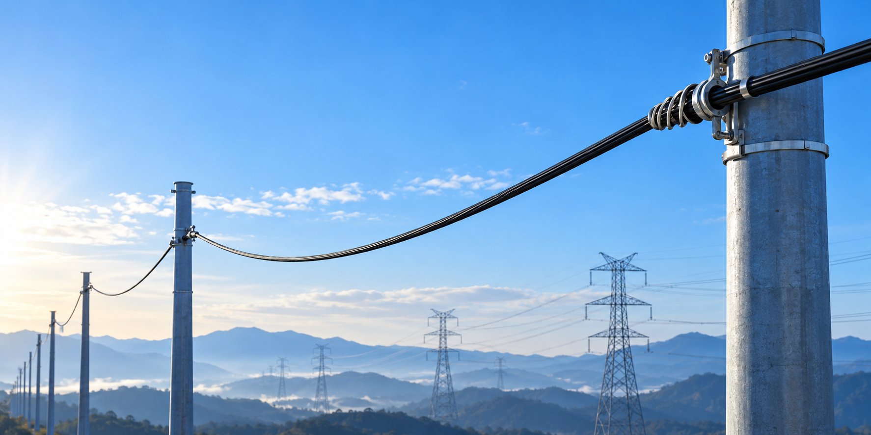
A complete buyer's guide to ADSS all-dielectric self-supporting fiber optic cable: construction, span and loading design, installation, testing, MOQ, warranty and quotation checklist for aerial power and FTTx routes.
When you plan an aerial fiber route along power distribution lines, railway corridors, or utility poles that already carry electrical infrastructure, one cable family will appear in almost every specification you compare: ADSS, or all-dielectric self-supporting fiber optic cable. It is the construction that lets a fiber cable span pole to pole on its own strength members, with no metal messenger wire, no lashing operation, and no bonding or grounding hardware at every support. That combination is why utilities, ISPs, and network contractors specify ADSS for aerial FTTx and power-corridor projects across Southeast Asia, the Middle East, Africa, and Latin America.
ADSS is also one of the most commonly mis-specified cable types in the industry. A cable that performs perfectly on a 60-meter span in a calm coastal town can fail in service on a 150-meter span in a mountain pass with heavy ice loading, because the aramid content, the rated tensile strength and the hardware were never sized for the real route. Most of these failures are not manufacturing defects; they are specification gaps that were visible in the inquiry stage and never closed.
This guide walks through the entire buying decision: what ADSS cable actually is and how it is built, when it is the right choice and when it is not, how span length, tension and wind and ice loading shape the design, what a competent factory checks before shipment, how installation and acceptance testing work, and what information you should prepare before requesting a quotation. The figures quoted for Nexora products are typical values for the standard range; the datasheet issued with your order governs, because every aerial route is calculated individually.
What Is ADSS Fiber Optic Cable?
ADSS stands for all-dielectric self-supporting. Both words describe a deliberate engineering choice. All-dielectric means the cable contains no metallic parts at all: no steel strength member, no armor, no copper wire. Tension is carried by aramid yarn, the same family of aramid fiber used in ballistic protection, and the central element is FRP, a glass-fiber-reinforced plastic rod. Self-supporting means the cable is designed to hang between structures on its own mechanical strength, without a separate steel messenger wire and without lashing wire.
Put the two properties together and you get a cable that can be installed on power poles and transmission towers without introducing a conductive path along the route. There is nothing to bond, nothing to ground, and no metallic path for induced current from nearby energized conductors. For network owners, that removes an entire category of hardware, inspection items and corrosion points from the route, and it allows the cable to occupy positions on a structure that would be unsafe or non-compliant for a cable with a metallic messenger.
Self-supporting does not mean the cable ignores physics. The cable still sags under its own weight, still responds to wind pressure and ice accumulation, and still transfers tension into every structure it attaches to. The difference is that the designer sizes the cable's internal strength members, instead of sizing an external messenger. That is why two ADSS cables with the same fiber count can have different diameters, different weights and very different prices: the aramid content has been calculated for different spans and different loading conditions.
Typical applications include aerial fiber along medium- and high-voltage distribution routes, FTTx backbone segments on existing utility poles, railway and highway corridor links, crossings over rivers and roads where adding a messenger is impractical, and retrofit installations on structures that have no spare capacity for a second support wire. Wherever the route shares structures with electrical infrastructure, the all-dielectric property is usually the deciding argument.
How an ADSS Cable Is Built
Understanding the construction helps you read a datasheet critically instead of comparing cables only by price and fiber count. From the center outward, a typical ADSS design includes the optical units, water-blocking elements, the FRP central strength member, aramid yarn, and one or two jackets. Each layer has a specific job, and each layer is a place where a low-cost cable can quietly cut corners.
The optical units hold the fibers in loose tubes or in a compact central-bundle arrangement, depending on the fiber count and the manufacturer's design. Loose-tube construction isolates the fiber from cable strain, which matters on aerial routes where the cable length changes with temperature and tension every single day. Water-blocking gel or dry water-swellable material inside the tubes and the cable core prevents moisture from travelling along the cable if the jacket is ever breached. The FRP central member provides compression resistance and keeps the cable round under the clamping pressure of suspension and tension hardware.
The aramid yarn is the defining layer. It is laid in a controlled helix around the core, and the total amount of aramid is calculated from the rated tensile strength the cable must achieve for your span and loading. More span, more wind, more ice, or tighter sag limits all translate directly into more aramid, a larger cable diameter and a higher price per kilometer. This is the single biggest reason ADSS cables are quoted per project rather than from a generic price list.
The jacket is usually a black, UV-stabilized polyethylene, applied as a single jacket on shorter-span designs or as an inner and outer jacket with the main aramid layer between them on longer-span designs. The double-jacket arrangement protects the aramid during installation and keeps the two load-bearing functions separate: the outer jacket resists the environment, while the aramid inside carries the tension. On routes running parallel to high-voltage conductors, a track-resistant jacket grade is often specified; more on that below.
When ADSS Is the Right Choice — and When It Is Not
The strongest case for ADSS is an aerial route that shares poles or towers with energized conductors. On a power distribution line, hanging a conventional cable from a steel messenger means every support point needs bonding and grounding hardware, the messenger must respect safe working distances from the conductors, and the whole run sits inside the lightning and fault-current environment of the line. An all-dielectric cable removes the messenger, the lashing wire and the grounding hardware in one decision, which shortens stringing time and removes the corrosion points that a steel messenger develops over years of outdoor exposure.
The second strong case is installation speed on pole-dense routes. ADSS is pulled in a single pass, clamped at each support, and done. There is no second pass to string and lash a messenger, no lashing machine to mobilize, and fewer opportunities for the sagging or misalignment problems that come from a two-component installation. For rural FTTx builds where labor, not cable, is the dominant cost, the single-pass property shows up directly in the project budget.
| Criterion | ADSS | Figure-8 self-supporting | Conventional cable + messenger |
|---|---|---|---|
| Metallic content | None | Steel or FRP messenger | Steel messenger |
| Grounding at supports | Not required | Required if steel messenger | Required |
| Installation passes | Single pass | Single pass | Two passes (string, then lash) |
| Suitability near live conductors | Excellent | Depends on messenger type | Limited by clearances |
| Typical economical span | Medium spans, calculated per route | Short to medium spans | Long spans with strong messenger |
| Cable cost per km | Highest | Medium | Lowest cable, highest hardware count |
ADSS is not automatically the right answer for every aerial route. For direct burial or duct installation, a standard loose-tube cable is the correct and far more economical family; ADSS's aramid content would be paid for and never used. For very long single spans — a wide river crossing, for example — a specialized high-strength design has to be calculated case by case, and in some of those cases a different construction or even a different aerial strategy wins. And on short urban spans where a steel messenger already exists and simply needs reuse, attaching a conventional cable to the existing messenger can still be the cheaper total solution. The right answer is decided by span, loading, structures and labor cost together, not by cable price alone.
The Four Inputs That Decide Your ADSS Design
Every competent ADSS manufacturer will ask you the same four questions before quoting: the longest span between supports, the local wind and ice loading, the required fiber count, and the electrical and physical environment of the route. If a supplier quotes your route without asking these questions, the quotation is a guess dressed up as a price, and the gap will surface either as an over-priced cable or as an in-service failure.
Span length
Span is the distance between support points, and it is the single strongest driver of cable design. Standard ADSS constructions in the Nexora range are calculated for spans up to 100 meters between supports, and reinforced constructions extend that to around 300 meters (typical values). The figure that matters is not the average span but the longest one, because tension in a self-supporting cable scales with the span it must cross. A route with mostly 50-meter spans and one 120-meter river crossing is designed for the 120-meter crossing; the rest of the route simply benefits from the margin.
Wind and ice loading
Wind pressure and ice accumulation add vertical and horizontal loads on top of the cable's own weight, and they multiply quickly: ice increases diameter and weight at the same time as it increases the surface exposed to wind. Two routes with identical 80-meter spans can need visibly different aramid content if one sits in a light-loading coastal district and the other crosses a mountain plateau with an established ice record. This is why serious suppliers ask for the local loading conditions, or the design standard your utility applies, instead of assuming a default.
Fiber count
ADSS in the Nexora range is available from 4 up to 144 fibers (custom configurations available). Fiber count affects diameter and weight, which in turn affect tension and sag, so it belongs in the design conversation rather than being filled in at the last moment. Choose the count for the network plan plus realistic growth headroom, because adding fibers later means re-running the span, and the cost of that second mobilization dwarfs the marginal cost of the extra fibers on the first installation.
Environment
Finally, describe the environment: the voltage class and position of nearby conductors, temperature extremes, pollution or coastal salt exposure, and any special crossings. These inputs decide jacket grade, the need for track-resistant material and the hardware family that will hold the cable for the next twenty years.
Rated Tensile Strength, Sag and Everyday Tension: The Numbers That Matter
ADSS datasheets are built around a small set of mechanical terms, and understanding them lets you compare two quotations on equal footing. The most important is RTS, the rated tensile strength: the maximum longitudinal load the cable is designed to withstand. RTS is not a working tension; it is the ceiling from which working limits are derived.
In normal practice, the maximum installation tension is kept well below RTS. A commonly used working figure, and the one quoted as typical for the Nexora ADSS range, is that installation tension stays at or below 20% of RTS. Keeping installation tension in this region preserves a large reserve for the loads that arrive later — wind, ice, temperature contraction, and long-term creep — and it keeps fiber strain inside the window where attenuation stays stable.
Sag is the other half of the same calculation. For any given span, tension and sag trade off against each other: pulling the cable tighter reduces sag and increases tension; leaving it slacker reduces tension and increases sag. The designer's job is to find the point where sag keeps the cable clear of third-party clearances and out of reach, while tension stays within the limits of the cable and the structures. On pole lines, the sag limit is often set by the clearance table your utility or telecom authority applies, not by the cable itself.
When you compare quotations, ask each supplier to state the assumed span, the assumed loading condition, the resulting RTS, and the expected sag at that span. Two cables can look identical in a table of fiber counts and jacket colors while being built for completely different routes. A quotation that states its assumptions is comparable; one that does not is asking you to accept an unknown.
Wind and Ice Loading: How Weather Changes the Cable
Many national and utility standards classify outdoor design conditions into loading districts — combinations of wind pressure, ice thickness and temperature — and cable designers translate those districts into mechanical requirements. The practical point for a buyer is that loading is not a detail to be confirmed after the order; it is a design input on the same level as span length. The same fiber count and the same span can produce two different cable diameters and two different prices depending on whether the route sees light coastal wind or a mountain district with a documented ice history.
Ice is the more punishing of the two loads. Radial ice increases the effective diameter of the cable, which increases both the weight per meter and the area exposed to wind, and it does so at the temperature where the cable materials are stiffest. In heavy ice districts, the aramid content needed to hold the same span can rise dramatically, and the economical answer sometimes changes: a shorter average span, additional poles, or a reinforced construction with a higher RTS become part of the conversation.
Wind matters most through span and height. Exposed, elevated routes accumulate more wind load than sheltered low-level routes of the same geographic area. If your route runs along a ridge, across open farmland, or on tall structures, say so explicitly in the inquiry. For projects where the loading condition is genuinely unknown, ask the supplier to state the loading assumption used in the design, and confirm it against the local standard before the design is frozen. The figures printed in a product brochure are starting points for comparison; the values calculated for your route and stated in the project datasheet are the ones that govern.
Choosing Fiber Count and Fiber Type for an Aerial Route
Fiber count on an aerial route is a planning decision with a mechanical consequence. Every additional fiber adds weight and diameter to the cable, which increases tension and sag on the same span. The practical approach is to size the count for the current network design plus a defined growth margin — many operators plan 20 to 50% spare fibers on distribution routes — and to communicate the final count to the cable designer before the mechanical calculation, not after. A 24-fiber cable and a 96-fiber cable for the same span and loading will not be the same physical cable.
For fiber type, G.652D single mode is the standard choice for aerial access and distribution routes, and it is the standard offering across the Nexora cable range. Typical attenuation for this fiber class is no more than 0.36 dB/km at 1310 nm and 0.22 dB/km at 1550 nm (typical values; the reel test report with your shipment shows the measured figures). Those numbers are what let an aerial route close its optical budget over many kilometers without amplification, and they are also a convenient acceptance benchmark: the measured attenuation of the installed route should be reconcilable with the reel reports plus known splice and connector losses.
If your project uses the route for a specific application — mobile fronthaul, PON distribution, or a leased dark-fiber segment — confirm the fiber type against the equipment that will terminate it. The cable itself is usually the least flexible element to change later, so the fiber decision deserves the same scrutiny as the mechanical one, even though it feels like the easier of the two.
Jacket Selection: PE and Track-Resistant Options
The default jacket for ADSS is a black, UV-stabilized polyethylene selected for long-term outdoor exposure. On the Nexora standard range this is a UV-resistant PE jacket rated for operating temperatures from -40°C to +70°C (typical values). For most distribution and FTTx routes, this is the correct and most economical choice, and it needs no further justification.
The exception is routes that run close to and parallel with high-voltage conductors for long distances. In that environment, the cable surface can accumulate charge and contamination, and in dry polluted conditions a standard PE jacket can, in documented industry experience, develop tracking — a progressive surface degradation that starts at contamination spots and grows into the jacket. For these routes, jacket materials with improved tracking resistance are a standard option across the ADSS industry. Whether your route needs it depends on the voltage class, the separation distance and the local pollution level, which is exactly the kind of question your supplier should be asking rather than leaving to you. If your utility has an established practice for ADSS jacket grades near transmission lines, follow it; if not, raise the question explicitly in the inquiry.
Jacket choice also interacts with hardware: the clamps that hold an AT-jacketed cable are specified with the jacket material in mind. Treat jacket grade, hardware and structure attachment as one decision package rather than three separate line items.
Hardware Planning: Suspension, Tension and Dead-End Points
The cable is only half of an ADSS system. The hardware that grips the cable at every pole determines whether the design's tension and sag numbers survive contact with the real route. Three hardware categories matter, and each is matched to the cable's diameter and jacket, which is another reason the cable and its fittings should be quoted together.
Suspension clamps support the cable at intermediate poles, where the cable continues through. They are designed to hold the cable without crimping it, usually with a helical or cushioned interface that spreads the load over a length of the cable surface. Tension and dead-end hardware anchor the cable where the route terminates or changes direction significantly. These grips take the full tension of the span, so they are sized for the cable's RTS, not just its diameter. Between them, intermediate fittings such as vibration dampers may be specified on longer or more exposed spans, following the supplier's span and loading recommendation.
Two practical rules keep hardware planning out of trouble. First, order hardware for the actual cable diameter and jacket of the calculated design, not for a nominal fiber count; a design change from 48 to 72 fibers changes the diameter and therefore the clamp size. Second, plan dead-end and slack-loop positions on the route drawing before the cable order is placed. Slack loops at each pole absorb daily thermal expansion and contraction and make future maintenance and re-splicing possible without re-stringing the span. A route drawing that shows hardware positions is also the fastest way for a supplier to check the reel length plan against the splicing plan.
Installation Best Practices: Stringing, Tension Control and Clearances
ADSS installation is mechanically simpler than messengered aerial cable, but simpler does not mean careless. The failures that occur in the field trace back to a small set of repeating causes, and all of them are preventable with standard discipline.
Before stringing, walk the route and confirm the assumptions: actual span lengths against the design, the condition of poles and hardware positions, and the clearances that the sag calculation assumed. Pay out the cable from the reel with controlled tension using a suitable tensioner or brake, and monitor pulling tension continuously with a dynamometer; the installation tension should remain within the limit stated in the project datasheet, which in typical designs means at or below 20% of RTS. Never pull ADSS over rough surfaces, through pulleys with tight radii, or around corners without suitable sheaves — the bend radius during installation should respect the standard guidance for the cable family, typically 20 times the cable diameter during installation and 10 times in service (typical values).
At each support, install the clamp type and position shown on the route drawing, and form the slack loop so it cannot abrade on the structure or flap in wind. Where the route passes close to energized conductors, the cable's dielectric construction removes the grounding requirement, but it does not remove the working-distance rules that protect the installation crew; access, positioning and safety clearances remain the responsibility of the installation team under the local electrical safety code.
After stringing, let the cable settle before final clamping and record the as-built sag at representative spans. On long routes, documenting actual tensions, sags and hardware positions pays for itself the first time a span needs inspection or a section needs re-sagging: the crew works from the as-built record instead of re-measuring the whole route.
Seven Common ADSS Installation Mistakes — and How to Avoid Them
- Sizing the cable for the average span instead of the longest one. Tension is set by the worst span. Identify the longest and most loaded span first and design for it.
- Ignoring wind and ice loading. A price that looks low because the loading assumption is light is not a saving; it is a deferred failure. State the loading condition in the inquiry.
- Over-tensioning during pulling. Exceeding the installation tension limit strains the fibers and can shift attenuation permanently. Use a tensioner and a dynamometer on every pull.
- Bending the cable too tightly at poles and corners. Respect the installation bend radius, typically 20 times the cable diameter, and use properly sized sheaves and blocks.
- Using hardware not matched to the cable. Clamps sized for the wrong diameter or jacket material creep, slip or cut in service. Order hardware with the cable, for the calculated diameter.
- No slack loops. Without service loops at poles, later maintenance and temperature movement work directly against the fiber. Plan loop positions on the route drawing.
- Skipping as-built documentation. Without recorded sag, tension and hardware positions, every future fault localization starts from zero. Keep the as-built record with the splice documentation.
None of these items is technically difficult. All of them are cheap to prevent at the specification stage and expensive to correct after the cable is clamped and energized alongside a live network. The pattern behind all seven is the same: decisions made before the order determine what is possible in the field.
Testing and Acceptance: What to Verify Before and After Installation
Acceptance testing on an ADSS route has two stages, and each one answers a different question. The first stage is at the factory and at reel receipt: every reel of Nexora ADSS cable is tested for attenuation and continuity before dispatch, and the test report accompanies the shipment. When the reels arrive, reconcile the reel labels against the order — fiber count, construction, lengths — and file the reports; they are the baseline for the second stage.
The second stage is after installation: an OTDR trace of each fiber, ideally bidirectional on longer routes to average out the directional signature of splice events, plus insertion loss measurements on any links that terminate on patch panels. Compare the measured attenuation with the sum of the reel reports plus expected splice loss plus connector loss. A route that reconciles within its budget is accepted with evidence; a route that does not reconcile has told you where to look before anyone excavates or re-strings anything.
Two documents make the acceptance file complete: the reel test reports and the as-built installation record with sags, tensions and hardware positions. Together they cover both failure domains of an aerial route — optical and mechanical — and they are the reference points for every warranty or in-service question later. If your contract specifies an acceptance standard, name it in the inquiry so the test documentation is produced in the right format the first time.
How Nexora Builds and Checks ADSS Cable
Nexora Communications has manufactured fiber optic cabling since 2014 at a 16,000+ m² facility in Shenzhen, with 180+ employees and 12 production lines. Annual capacity is 2.8M+ units and monthly capacity is 230K+ units across the product families, with ADSS production scheduled per order because the aramid content and construction are calculated for each route. Quality control runs through incoming material, component, in-process, functional, visual, final and packaging inspection at 30+ QC stations, and the company has completed 500+ OEM/ODM projects for customers in 50+ countries and regions.
For an ADSS order, the practical meaning of that process is straightforward. The design inputs you provide — fiber count, span, loading, jacket grade — are confirmed against the calculated construction before production. Incoming aramid and jacket materials are inspected before they enter the line. During production, the cable is checked against the approved datasheet, and every reel is tested for attenuation and continuity before packing, with the test report supplied with the shipment. If a project requires a specific reel length plan so that splices fall where the route drawing wants them, that plan is agreed at order confirmation and followed on the line.
Nexora also supplies OEM and ODM manufacturing for aerial cable programs: fiber count, construction, jacket grade, jacket printing and reel length can be built to your project specification and delivered under your brand, with the same design-confirmation and QC process behind every configuration.
MOQ, Lead Time, Packaging and Export Logistics
On the standard range, the minimum order quantity for ADSS cable is 1,000 m per configuration (typical). Because the aramid content changes with the span and loading of your route, the exact MOQ is confirmed together with the confirmed construction. Typical production lead time is 15 to 25 working days after the drawing and the order are confirmed, and it runs longer for reinforced constructions or large fiber counts — one more reason to close the design inputs early rather than late.
ADSS cable is supplied on wooden reels with an outer protective wrap and a reel label showing fiber count, length and construction. Reel length is not an afterthought: it is set from the span pattern and the total route length so that splicing points fall where the route plan wants them, which reduces splice closure count and installation time. Custom reel lengths and marking can be arranged with the order, and export packing is standard.
When you plan logistics, ask for the drum dimensions and gross weight with the quotation so freight and site handling can be scheduled, and confirm whether your crew needs the cable delivered in a specific sequence for the stringing plan. On routes with staged installation, staged delivery against the stringing schedule is often simpler than storing every reel on site from day one.
Warranty and After-Sales Support
All Nexora fiber optic cables, including the ADSS range, carry a 12-month warranty from the shipment date, covering manufacturing defects. The warranty does not cover damage from over-tensioning during installation or from site conditions outside the agreed specification — which is exactly why installation tension discipline and correct hardware matter beyond their engineering value: they keep the failure domains separate and the responsibilities clear.
If a defect is confirmed within the warranty period, the affected cable length is replaced or credited. A claim is raised by sending the reel label, the order number and photos of the defect to the sales contact, which allows the claim to be traced to the production record and the reel test report. This 12-month term is the standard warranty across the entire Nexora product range, so a mixed project — cables, patch cords, adapters on the same order — carries one consistent warranty condition instead of a patchwork.
Total Cost of Ownership: Comparing ADSS Quotations the Right Way
ADSS cable costs more per kilometer than a conventional loose-tube cable, and comparing quotations on cable price alone always reaches the wrong conclusion. The honest comparison is the installed route cost: cable, hardware, structure preparation, labor passes, and the long-term maintenance profile of each option.
Against a messengered installation, ADSS removes the messenger purchase, the lashing operation, and the grounding hardware and bonding labor at every support. On a route with hundreds of support points, those items are not rounding errors; on some routes they exceed the cable price difference entirely. Against a Figure-8 construction, the comparison runs through span capability and electrical environment: where the route approaches energized conductors, the all-dielectric construction is not a premium but a requirement, and where spans are long and heavily loaded, the calculated aramid content decides what is actually buildable.
Then compare the ADSS quotations against each other on assumptions, not on unit price. The quotation that states its span, loading, RTS, sag and jacket assumptions lets you verify the design; the one that is cheapest without stating assumptions is transferring a design risk to you that will surface after the cable is on the poles. Ask every bidder to quote on the same declared route data, and the price comparison becomes meaningful on its own.
ADSS Buyer Checklist: What to Send for an Accurate Quotation
A complete inquiry gets a complete quotation in one round instead of three. Before you request pricing, assemble the following:
- Route length and the longest span between supports, plus any special crossings (rivers, roads, railways).
- Pole or tower spacing pattern and the structures the cable will attach to.
- Local wind and ice loading, or the design standard and loading district your utility applies.
- Required fiber count, including planned growth margin.
- Fiber type requirement (standard offering is G.652D single mode) and any application constraints.
- Voltage class and proximity of parallel energized conductors, for the jacket grade decision.
- Temperature range, pollution or coastal exposure, and terrain profile where relevant.
- Preferred reel lengths and the splicing plan, if one exists.
- Whether OEM/ODM branding, jacket printing or custom labeling is required.
Send those items and a supplier can confirm the construction, the RTS and the reel plan together with the price. Omit them and every number in the reply is provisional — including the price.
Frequently Asked Questions
What does ADSS actually stand for?
All-dielectric self-supporting. All-dielectric means the cable contains no metallic components; self-supporting means it carries its own weight between structures without a separate messenger wire or lashing.
How long can an ADSS span be?
Standard constructions in the Nexora range are calculated for spans up to 100 m between supports, and reinforced constructions up to around 300 m (typical values). The buildable span for your route is calculated from span, loading and sag limits, and confirmed in the project datasheet.
Does ADSS cable need grounding?
No. Because the cable contains no metal, there is no conductive path to bond or ground at the supports. The installation crew still follows the electrical safety clearances applicable to working near energized conductors.
What is the MOQ for ADSS cable?
The standard minimum order quantity is 1,000 m per configuration (typical). The exact MOQ is confirmed together with the calculated construction for your route.
What is the typical lead time?
Typically 15 to 25 working days after the drawing and order are confirmed, longer for reinforced constructions or large fiber counts. Confirm the schedule for your configuration at order stage.
Can ADSS cable be customized or made under our brand?
Yes. Fiber count, aramid content, jacket grade, jacket printing and reel length can be built to your project specification under Nexora's OEM/ODM program, which has delivered 500+ projects for customers in 50+ countries.
What is the difference between ADSS and Figure-8 cable?
Figure-8 cable bonds the optical core to an integrated messenger (steel strand or FRP) in one profile, so it installs in a single pass but includes a metallic member unless FRP is chosen. ADSS has no messenger at all and carries its load with internal aramid, which is why it is preferred near energized conductors. Figure-8 is often the economical choice on shorter spans where a metallic member is acceptable.
What warranty applies?
All Nexora fiber optic cables carry a 12-month warranty from the shipment date covering manufacturing defects. Claims are raised with the reel label, order number and defect photos; confirmed defects are replaced or credited.
How is the cable packed for export?
On wooden reels with an outer protective wrap and a reel label showing fiber count, length and construction. Reel lengths are planned from the span pattern so splice points fall where the route plan wants them, and custom lengths and marking can be arranged.
What tests does the cable undergo before shipment?
Every reel is tested for attenuation and continuity before dispatch, and the test report accompanies the shipment. In-process quality control covers incoming material, component, in-process, functional, visual, final and packaging inspection at 30+ QC stations.
What attenuation should I expect?
For the standard G.652D single mode fiber, typical values are no more than 0.36 dB/km at 1310 nm and 0.22 dB/km at 1550 nm. The measured values for your reels are on the test report supplied with the shipment; the installed route is reconciled against those reports plus splice and connector losses.
Can you supply a sample before we order?
Yes. A short cable sample for evaluation can be supplied. Tell us the fiber count and the construction you are considering and the sample arrangement will be confirmed with you.
The Bottom Line
ADSS is the right choice when your aerial route lives on power structures, when installation speed across many spans matters, and when the route must add no conductive path to an existing electrical environment. It is the wrong choice for buried and duct routes, and on very long or extremely loaded spans it has to be engineered rather than bought from a table. The cable that performs for twenty years is the one whose span, loading, fiber count and environment were stated clearly in the inquiry and confirmed in a calculation before production started.
If you are evaluating ADSS for an upcoming route, send us the fiber count, the longest span, the pole spacing and the wind and ice loading of the route, and our team will confirm the construction, the reel plan and the pricing — and if your project also needs matching connectivity, our LC-LC duplex single mode patch cords, SC/APC adapters and outdoor G.652D single mode fiber optic cable round out the same aerial and backbone design. You can also compare this construction with our Figure-8 self-supporting cable if some segments of your route allow a metallic messenger.
All performance figures in this article are typical values for reference; the datasheet issued with your order governs. All Nexora products carry a 12-month warranty from the shipment date.