
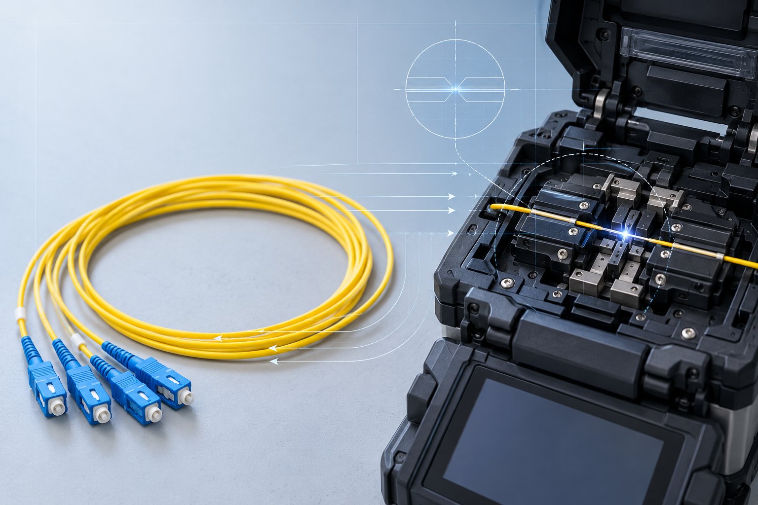
What is a fiber optic pigtail, how is it made, and how do you specify SC, LC, FC or ST pigtails? A 2026 B2B buyer's guide to insertion loss, return loss, UPC vs APC, and fusion splicing from Nexora.
What Exactly Is a Fiber Optic Pigtail?
A fiber optic pigtail is a short, tight-buffered length of optical fiber with a factory-installed connector on one end and an exposed, unterminated fiber on the other. The unterminated end is designed to be fusion spliced onto a cable, a backbone fiber, or another fiber assembly, while the connectorized end plugs into an adapter, a patch panel, or an active device. In other words, a pigtail is the bridge between a field cable that has no connector and the structured, connectorized world of racks, panels, and equipment. This single-ended design is not a limitation; it is the whole point. Because the connector is attached in a controlled factory environment rather than in a dusty street cabinet or a cramped splice tray, the finished end face can be polished, inspected, and tested to a consistency that field installation simply cannot match.
The term is sometimes confused with related assemblies, so it helps to be precise from the start. A patch cord has connectors on both ends and is used to connect two ports directly. A pigtail has one connector and one bare fiber end. A splice-on connector combines a stub of fiber with a connector that is spliced in the field. Each product has its place in a network, and choosing between them is one of the most practical decisions a buyer, contractor, or network engineer makes during project planning. This guide explains what a pigtail is, how it is manufactured, where it is used, and how to specify one so that the splices you make today remain stable for years.
At Nexora, pigtails sit alongside patch cords, adapters, and indoor and outdoor cables as part of a complete fiber optic product line manufactured in our Shenzhen facility. Since 2014 the company has grown to more than 180 employees working across 12 production lines in over 16,000 square meters of manufacturing space, producing more than 2.8 million units annually and supporting over 500 OEM and ODM projects for customers in more than 50 countries. That production experience is the basis for the practical detail in this article: what actually matters when you order pigtails in volume, and which specification lines deserve your attention before you sign an RFQ.
Pigtail vs Patch Cord vs Splice-On Connector: Which Assembly Fits Your Project?
Understanding the boundaries between the three common fiber assemblies prevents one of the most frequent procurement mistakes: ordering the wrong product for the termination method the crew will actually use on site.
The patch cord: connectors on both ends
A patch cord, sometimes called a patch cable or jumper, terminates in a connector at both ends. It is the assembly you see filling the front of a data center patch panel, connecting a switch port to a panel port, or linking an ONU to an NTU at a subscriber premise. Patch cords are field-ready out of the box: no splicing, no polishing, no consumables. The trade-off is that both ends occupy adapter space, and the cable must be routed intact from port to port, which is why patch cords dominate horizontal cabling and equipment interconnection but rarely appear inside splice closures.
The pigtail: one connector, one splice
A pigtail terminates in a connector at one end only. The other end is a short length of bare, 900-micron tight-buffered fiber that the installer strips, cleaves, and fusion splices to a cable fiber inside a splice tray. Once spliced and protected with a heat-shrink splice protector, the assembly delivers the cable's signal to a factory-quality connector. This is the standard method for terminating indoor and outdoor cables at an ODF, cross-connect cabinet, or wall-mounted termination box. The splice adds one attenuation point, but a well-made fusion splice typically contributes a very small fraction of a decibel, and in exchange the network receives a connector whose geometry and polish were verified in a factory rather than improvised on a ladder.
The splice-on connector: connector and stub in one
A splice-on connector (SOC) packages a short fiber stub and a connector into a single body that is spliced directly to the cable fiber. It saves a separate splice protection step and keeps the termination compact, which is why it is popular in FTTH drop terminations and space-constrained enclosures. Compared with a discrete pigtail, an SOC shifts more precision into the field operation, because the connector's factory polish is fixed but the splice is still made by the crew. For large ODF builds where splice trays are already organized, discrete pigtails remain easier to inventory, label, and replace individually.
How to decide
Use patch cords wherever two ports meet and no permanent termination is needed. Use pigtails wherever a cable must be brought into a panel, cabinet, or closure and terminated with a factory-quality connector. Use splice-on connectors where space is tight or where your crews are already equipped and trained for SOC installation. Most projects use all three: pigtails terminate the cable plant, patch cords connect the electronics, and SOCs handle the awkward corners. The cost comparison should therefore include labor, not just unit price; a slightly cheaper termination method that adds minutes per splice across thousands of subscribers quickly erases its own discount.
Anatomy of a Fiber Optic Pigtail: Every Layer Explained
Although a pigtail looks like nothing more than a connector on a wire, each component layer is an engineering decision that affects loss, reliability, and installation behavior. Understanding the anatomy also gives you the vocabulary to read a datasheet line by line instead of trusting a single headline number.
The optical fiber itself
The fiber is the functional core of the assembly. Single mode pigtails most commonly use G.652.D fiber, the workhorse of metropolitan and access networks, offering low attenuation around 1310 nm and 1550 nm and compatibility with virtually all legacy and current transmission equipment. Where the routed path includes tight bends, such as compact wall boxes or FTTH drop terminations, bend-insensitive G.657.A1 or G.657.A2 fiber is preferred because it tolerates bend radii several times smaller than standard fiber with minimal added loss. Multimode pigtails use OM1, OM2, OM3, OM4, or OM5 fiber graded by bandwidth: OM3 supports 10 Gbps over 300 meters with laser-optimized 50-micron core, OM4 extends that class to 400-550 meters and underpins 40G and 100G short-reach links over parallel lanes, and OM5 adds wavelength-division support for shortwave wavelength-division multiplexing. Matching the pigtail fiber to the cable fiber is not optional; splicing G.652.D to G.657.A1 works well, but splicing single mode to multimode is a mode-field mismatch that no splice recipe can fix.
Buffer, strength member, and jacket
The fiber in a pigtail is protected by a 900-micron tight buffer, a plastic layer extruded directly over the coating that gives the bare fiber enough stiffness to be handled, routed, and stripped cleanly. Beyond the buffer, most pigtails add aramid yarn (Kevlar) as a tensile strength member, which absorbs pulling force so it never reaches the glass. The outer jacket is typically 2.0 or 3.0 mm PVC for standard indoor use, or LSZH (low smoke zero halogen) where fire regulations or enclosed spaces demand it, such as data centers, tunnels, ships, and public buildings. Jacket diameter also matters mechanically: a 3.0 mm jacket offers better crush and pull protection for ODF work, while a 0.9 mm fan-out style is used inside equipment where space is at a premium.
The connector body and boot
The connector consists of a ferrule, the precision-aligned ceramic sleeve that holds the fiber; a body that locks into the adapter; and a boot that transitions from connector to jacket while absorbing flex. Zirconia ferrules dominate because their thermal expansion matches silica fiber and their surfaces polish to sub-micron smoothness. Ferrule concentricity, the alignment between fiber core and ferrule axis, is a key internal quality metric: tighter concentricity means lower insertion loss variability from piece to piece, which matters enormously when a purchasing team orders thousands of pigtails and every one must perform like the sample that was approved.
End face polish: UPC and APC
The fiber end inside the ferrule is polished either flat with a slight microscopic dome (UPC, ultra physical contact) or at a typically 8-degree angle (APC, angled physical contact). UPC end faces reflect returning light straight back down the fiber, achieving return loss commonly in the range of 50 dB or better on a well-made single mode pigtail. APC's angled polish redirects reflected light into the cladding, pushing return loss to typically 60 dB or better, which is why APC is specified for FTTH, CATV, RF-over-glass, PON, and DWDM systems where reflected light would degrade laser performance or analog signal quality. The two polish types are not interchangeable: mating UPC to APC leaves an air gap that adds insertion loss and damages both end faces over repeated matings. A disciplined network chooses one polish standard per section and keeps adapters color-keyed, green for APC and blue for UPC single mode.
How a Factory-Manufactured Pigtail Is Made, Step by Step
Buyers often assume all pigtails are equivalent because they look alike. The manufacturing process is where quality is actually created, and understanding it explains why two visually identical assemblies can differ in performance and lifespan.
Step 1: Fiber cutting and preparation
Production begins with verified fiber reels. The fiber is cut to length with precise allowance for routing through the connector body and boot, then cleaned. Length accuracy matters because pigtails are stocked in standard lengths and spliced into trays with limited slack; a pigtail cut too short becomes waste on the installer's bench.
Step 2: Epoxy injection and fiber insertion
A metered amount of injection epoxy is placed into the ferrule, and the stripped fiber is inserted so that its end protrudes slightly beyond the ferrule face. This protrusion is what will later be polished down to a flush, domed finish. The epoxy is heat-cured in ovens under controlled time and temperature. Incomplete curing is a classic hidden defect: the assembly may pass a factory test, then shift its loss or fail catastrophically months later when thermal cycling in the field softens the bond.
Step 3: Curing and cooling
Cured connectors are cooled to room temperature before handling so the epoxy-fiber-ferrule bond stabilizes. Rushing this stage introduces micro-stress at the fiber, which can appear later as temperature-dependent loss drift, one of the hardest field faults to diagnose because the symptom moves with the weather.
Step 4: Scribe and polish
The protruding fiber tip is scribed and broken flush, then polished in progressive stages, typically from a coarse lapping film through finer grades to a final polish that defines the end-face geometry: apex offset, radius of curvature, and fiber height, the three parameters measured by 3D interferometric inspection. End-face geometry is what allows physical contact across the full glass core area. Poor geometry concentrates force on one side of the fiber, producing high loss, end-face damage, and intermittent signals under vibration or re-mating.
Step 5: Inspection and geometry measurement
Every finished end face is inspected under magnification for scratches, pits, epoxy residue, and contamination, and sampled (or, for critical orders, 100% measured) on an interferometer against industry geometry limits. Contamination deserves special mention: a speck of dust invisible to the eye across a 125-micron fiber can attenuate a link severely, which is why factory inspection and sealed packaging go together.
Step 6: Assembly with jacket and strength member
The connectorized stub is joined to the buffered fiber and jacket, with aramid yarn secured at the boot so tensile loads transfer to the connector body, not the fiber. Boots are crimped or bonded according to connector design, and strain relief is verified by pull testing on production samples.
Step 7: Optical testing
Finally, each pigtail is tested on a light source and power meter or an insertion loss meter for the wavelengths it will serve, with results recorded against specification limits. Insertion loss and return loss are the headline numbers; reputable manufacturers also track lot-level statistics, because a distribution shifted close to the limit is a warning even when every individual unit technically passes.
Why the process explains the price
This sequence, seven controlled stages with inspection gates, is what separates a pigtail that performs identically at installation and five years later from one that drifts. It also explains price differences between suppliers that look unjustified on a spreadsheet. Epoxy curing, geometry verification, and 100% loss testing consume real time and equipment capacity; skipping them is invisible at delivery and expensive in service. When Nexora quotes a pigtail, the price reflects that every unit is tested before packing, backed by a 12-month warranty from shipment date, and produced on lines that also build the patch cords and adapters it must mate with, so ferrule and adapter tolerances are managed as one system rather than left to chance across vendors.
Connector Types Compared: SC, LC, FC, and ST Pigtails
Connector choice determines compatibility with existing panels and equipment, packing density, and handling ergonomics. The four most common families cover nearly all international B2B demand.
SC: the access network standard
The SC (subscriber connector) uses a 2.5 mm ferrule in a square, push-pull body. Its large, stable footprint and snap-in latching made it the default for FTTH ONTs, media converters, and ODF ports, especially across Asia, Europe, and Latin American operator networks. SC pigtails are easy to handle with gloves, hard to cross-thread, and simple to label, which reduces installation errors on high-volume rollouts. The trade-off is density: at roughly 14 by 20 mm per port, SC consumes panel space quickly in high-count racks.
LC: the high-density choice
The LC (lucent connector) uses a smaller 1.25 mm ferrule in a compact latched body about half the SC footprint, making it the standard for data centers, enterprise switches, and SFP transceiver ports, which accept LC by default. LC duplex configurations pair two connectors on a shared boot for polarity-managed transmit and receive paths. For a data center buying pigtails to terminate riser or distribution cable at a patch panel that then feeds LC patch cords to switches, LC is usually the only sensible choice simply because the equipment side speaks LC.
FC: the threaded veteran
The FC (ferrule connector) secures with a threaded nut on a 2.5 mm ferrule. The screw-down mechanism resists vibration and accidental disconnection, which keeps FC alive in test equipment, CATV headends, industrial environments, and older carrier plant. FC pigtails remain in steady demand for maintenance and expansion of these installed bases. Installers should torque FC connectors to specification rather than hand-tightening where return loss matters, because over-tightening deforms the end-face contact.
ST: the legacy bayonet
The ST (straight tip) uses a 2.5 mm ferrule with a bayonet twist lock, familiar from older campus and industrial multimode installations. New designs rarely specify ST, but large installed bases in factories, ports, and universities keep ST multimode pigtails in regular supply for repair and expansion work. Nexora's ST multimode adapter and pigtail offerings exist precisely for these long-lived networks where replacing an entire infrastructure to abandon one connector family would be uneconomical.
Choosing between them
The practical rule is to match the panel and equipment ecosystem first, then standardize. Mixed-connector racks multiply adapter inventory, confuse crews, and complicate spares planning. Where new capacity is being built, LC maximizes density; where operator outside plant dominates, SC maximizes compatibility; where vibration or test benches dominate, FC earns its threads. When in doubt, send your panel photos and equipment models to your supplier and ask them to confirm the full interconnect chain, connector to adapter to patch cord, before ordering volume.
Single Mode vs Multimode Pigtails: Matching Fiber to the Network
The fiber type inside the pigtail must match the cable plant and the transmission equipment, and the two families are not interchangeable at any price.
Single mode pigtails
Single mode fiber, with a 9-micron core, carries light in one mode and supports long distances at high bandwidth, from metropolitan rings to long-haul routes and all PON-based FTTH. Standard G.652.D pigtails cover the majority of demand. For deployments where the pigtail routes through tight bend zones, G.657 bend-insensitive fiber avoids the loss penalty that standard fiber suffers at small radii, typically only a few centimeters for G.657.A2 class compared with roughly 30 mm for conventional single mode. Attenuation for both classes is typically specified at or below about 0.36 dB/km at 1310 nm and 0.22 dB/km at 1550 nm in cable form, with assembly-level loss dominated by the connector and splice rather than the short fiber length itself.
Multimode pigtails
Multimode fiber, with a 50-micron (laser-optimized) or legacy 62.5-micron core, carries multiple light modes and serves short-reach links inside buildings and data centers where its larger core simplifies connectorization and transceivers cost less. OM3 supports 10 Gbps to 300 m, OM4 extends to 550 m at that rate and enables 40G/100G short-reach over parallel lanes to 100-150 m, and OM5 formalizes multi-wavelength operation for emerging SWDM applications. Multimode link budgets are sensitive to modal bandwidth and mode conditioning, so the pigtail, patch cords, and backbone should all stay within one fiber grade to avoid blending bandwidth classes unknowingly.
Making the choice
Follow the network, not the datasheet: the pigtail inherits the fiber type of the cable it will be spliced to, and the transmission plan that was designed for it. The one deliberate exception is bend-critical routing, where substituting G.657 fiber for G.652.D inside an otherwise standard single mode plant is an accepted, low-risk upgrade because the fibers splice together cleanly. Where a supplier offers both, ask which fiber reel brand and standard the current production run uses; consistency across your volume order is worth more than a nominal datasheet improvement.
Where Pigtails Are Used: ODF, FTTH, Data Centers, and Beyond
Pigtails are invisible once installed, which is why buyers sometimes underestimate how many their projects consume. The main application families each impose slightly different requirements.
ODF and cross-connect termination
In an optical distribution frame, incoming outdoor cable fibers are spliced to pigtails whose connectors face the front of the frame, turning each raw glass fiber into a pluggable port. High-count ODF builds consume pigtails by the hundreds or thousands, and the specification that matters most here is consistency: uniform connector color coding, uniform length for tidy splice trays, and loss values that fall in a narrow distribution so link budgets can be designed once and trusted everywhere.
FTTH access networks
In fiber-to-the-home builds, pigtails terminate distribution and drop segments in cabinets, joint closures, and subscriber-facing boxes. APC polish dominates this segment because PON and RF video services are sensitive to reflections. Bend-insensitive fiber helps in the shallow boxes typical of apartment entrances, and LSZH jackets are commonly required in multi-dwelling buildings. The drop-side economics resemble those of FTTH drop cables: termination minutes multiply across thousands of homes passed, so assembly designs that simplify splicing and routing translate directly into rollout speed.
Data centers and enterprise backbones
Data centers terminate riser and horizontal cables at patch panels with LC pigtails, then interconnect equipment with LC or MPO/MTP patch cords. Airflow management and density push toward compact connectors and bend-tolerant fiber in slim jackets; fire codes push toward plenum-rated or LSZH constructions. Since a single rack may terminate dozens of links, buyers in this segment care most about geometric consistency of end faces, because a panel full of marginal connectors becomes a diagnostic nightmare under live traffic.
Industrial, CATV, and test environments
Factory floors, substations, railways, and ports subject plant to vibration, dust, and temperature swings, where FC threaded pigtails and armored constructions hold connections stable. CATV headends specify APC everywhere reflections would pollute analog signal quality. Test laboratories value FC pigtails for repeatable, torque-controlled mating during measurement campaigns. Across all of these, the pigtail is doing the same job, converting field glass into a factory-grade connector interface; only the environmental margins change.
How to Specify a Fiber Optic Pigtail: A Practical 10-Point Checklist
A clear specification prevents almost every pigtail procurement problem. Before requesting quotes, write down the following ten decisions; a capable manufacturer will confirm them in a day and return a matching datasheet.
- Connector type: SC, LC, FC, ST, or a mix; confirm against your panels, adapters, and equipment ports, including whether duplex boots are needed for LC.
- Polish type: UPC or APC, decided by the reflection budget of the systems running over the link; PON, CATV, and DWDM typically demand APC.
- Fiber type and standard: G.652.D or G.657.A1/A2 single mode, or OM2/OM3/OM4/OM5 multimode, matching the cable plant you will splice to.
- Fiber count per assembly: simplex or duplex/fan-out configurations, and how they map to your splice tray layout.
- Length: standard lengths such as 1 m or 1.5 m suit most ODF work; custom lengths avoid excess slack in shallow cabinets, and consistency across an order keeps trays tidy.
- Jacket material and diameter: PVC or LSZH, 0.9/2.0/3.0 mm, chosen for fire code compliance and mechanical protection.
- Insertion and return loss grades: typical assembly grades are insertion loss at or below 0.3 dB (with 0.5 dB an absolute maximum common in datasheets) and return loss at or above 50 dB UPC or 60 dB APC for single mode; ask for the actual grade each lot is tested to.
- Testing and documentation: 100% test with recorded per-unit values for large orders, plus end-face interferometry reports on request; this is standard practice at an established factory and worth confirming explicitly.
- Packaging and labeling: individual bags with dust caps, coil ties, printed labels carrying connector type, fiber type, and length; orderly packaging measurably reduces installation damage and time.
- Warranty and after-sales terms: confirm coverage in writing; Nexora supplies all fiber assemblies with a 12-month warranty from shipment date, applied uniformly across the product line.
Two of these lines deserve extra emphasis in international B2B purchasing. First, loss grades must be read as tested values, not marketing phrases; a supplier who can print per-unit test data alongside each carton has already answered most of your quality questions. Second, uniformity beats individual excellence: an order whose every unit measures 0.15 dB is easier to design with than one swinging between 0.05 and 0.45 dB, even if both technically comply. Ask prospective suppliers for lot statistics, not just pass/fail.
Quality Indicators: What the Numbers on a Pigtail Datasheet Mean
Reading a pigtail datasheet confidently requires only a handful of parameters, but each one hides a decision.
Insertion loss
Insertion loss is the signal power lost through the assembly, measured in decibels. For a factory pigtail, typical grades sit at or below 0.3 dB, with datasheet maximums commonly 0.5 dB. The number combines connector loss, fiber attenuation over the assembly length, and (in a spliced link) the splice loss downstream. When comparing quotes, check whether values are stated as typical, maximum, or tested; a typical 0.3 dB claim with no maximum is an invitation to receive whatever falls off the line that day.
Return loss
Return loss measures how much light reflects back toward the source. Higher is better. Single mode UPC assemblies commonly achieve 50 dB or better; APC assemblies 60 dB or better. Systems with lasers sensitive to reflections, PON optics, RF overlay, coherent DWDM, treat return loss as a hard requirement, not a preference. Multimode assemblies historically specify 20-35 dB classes because multimode transceivers tolerate far more reflection; do not compare multimode return loss against single mode expectations.
End-face geometry and interferometry
Apex offset, radius of curvature, and fiber height describe the microscopic shape of the polished ferrule tip. Standards bodies publish acceptable ranges, and interferometers verify each parameter in seconds. Geometry is invisible on a light meter yet explains many field failures: two assemblies each measuring fine in isolation may mate poorly because their radii combine to put contact pressure off-center. A factory investing in geometry measurement is a factory whose connectors mate predictably with other vendors' adapters.
Environmental and mechanical tests
For demanding environments, ask about test coverage: temperature cycling across the operating range specified for your region, vibration for industrial or mobile applications, tensile pull on boots and crimps, and repeated mating durability (commonly 500 or 1,000 matings in connector standards). You do not need every test on every order, but a supplier who can produce current test reports on demand has demonstrated the process control behind them.
Fusion Splicing Pigtails Correctly: Field Practices That Protect Factory Quality
The pigtail arrives perfect; the splice determines how much of that quality survives into service. Field crews following a few disciplines routinely achieve splice losses of a small fraction of a decibel.
Prepare a clean, controlled workspace
Splicing inside a closure or cabinet exposes fiber to dust and wind. Use the closure's splice tray as the work surface, keep the fusion splicer out of direct airflow, and strip and clean fibers immediately before cleaving. Isopropyl alcohol and lint-free wipes are consumables that must be treated as consumables: a wipe used twice is a contamination source.
Cleave squarely and splice promptly
A good cleaver producing near-perpendicular cleave angles is the single highest-leverage tool in pigtail termination. Modern splicers display estimated splice loss from cleave and alignment geometry; crews should treat any estimate above their project threshold (often 0.1 dB) as a redo trigger, not a pass. Protect every splice immediately with a heat-shrink protector sized to the tray, and route pigtail slack without bending below the fiber's specified minimum radius; G.657 fiber forgives tight routing, but the cable fiber being spliced to may not.
Test what you spliced
Record insertion loss through each finished link with a source and meter, or verify with an OTDR trace for long runs. Documentation per fiber, even a simple spreadsheet, turns a future fault from a day of guessing into a ten-minute lookup. Crews that label both the splice tray position and the panel port cut diagnosis time again; unlabeled quality is indistinguishable from junk at 2 a.m.
Handle end faces like optics, not hardware
Every mating wears the end face slightly. Keep dust caps on until the moment of connection, clean with one-click tools before each mating, and inspect suspect ports rather than blindly re-mating, which grinds contamination into the polish. A pigtail that survives installation with its end face intact will outlive several generations of the equipment connected to it.
Common Mistakes Buyers Make with Pigtails, and How to Avoid Them
Across hundreds of OEM and ODM projects, the same handful of procurement errors appears repeatedly. Each is cheap to prevent and expensive to discover on site.
- Mixing polish types in one segment. A single UPC pigtail spliced into an APC PON plant adds reflection exactly where the design forbids it. Standardize per segment and color-code adapters.
- Ordering all one length. Deep floor cabinets and shallow wall boxes need different slack. Ordering three lengths (for example 0.5 m, 1 m, 1.5 m) in the ratio your site surveys suggest wastes less and installs faster than one-size-fits-all.
- Ignoring the splice budget in link calculations. Each pigtail adds a splice; a 24-fiber cable terminated at both ends adds 48 splice losses to the span. At a fraction of a decibel each it is rarely decisive, but in long PON splits it belongs in the calculation.
- Buying on unit price alone. The cheapest pigtail that passes a spot check may still carry wide loss distribution, unverified geometry, and no test records. Field failures cost multiples of the unit saving.
- Skipping sample approval for large volumes. For orders beyond a few hundred units, approve a sample from the actual production run, not a showroom piece, then hold the volume to that reference.
- Forgetting consumables and accessories. Splice protectors, heat-shrink oven sleeves, cleaning tools, and adapters are part of the termination bill of materials; a shipment of pigtails without them stalls crews.
- No documentation request. Test data, reel traceability, and interferometry reports are free to ask for at PO stage and unavailable after delivery. Put them in the RFQ.
Customization and OEM/ODM: What a Manufacturer Can Tailor for You
Standard catalog pigtails cover most demand, but volume buyers regularly need tailored configurations, and this is where working directly with a manufacturer rather than a trader changes the outcome.
Typical customization dimensions include non-standard lengths to fit specific cabinet models; duplex and multi-fiber fan-out assemblies that split a breakout jacket into individual connectors; special jacket colors matching a customer's identification scheme; custom label content with part numbers, barcodes, or QR codes; packaging formats matched to the buyer's warehouse and kitting process; and combined kits pairing pigtails with matching adapters and patch cords so the entire termination interface arrives as one verified system. Lead times for customized orders depend on configuration complexity and volume, and buyers should confirm them against their project schedule rather than assuming catalog availability.
Nexora's OEM and ODM track record spans more than 500 projects across 50+ countries, supported by over 3,500 product configurations and roughly 300 new configurations developed each year. For a buyer, the practical meaning is straightforward: fiber type substitutions, connector combinations, labeling, and packaging are routine engineering tasks when they are handled by the same factory that produces the standard line, and a 12-month warranty from shipment date applies to customized assemblies on the same terms as catalog products. The most valuable contribution a buyer makes to a customization project is complete information at the start: the panel or closure drawings, the connector and polish standard, the fiber types on both splice ends, and the environmental conditions the assembly will face.
Frequently Asked Questions About Fiber Optic Pigtails
What is the difference between a fiber optic pigtail and a patch cord?
A patch cord has connectors on both ends and connects two ports directly. A pigtail has one connector and one bare fiber end that is fusion spliced to a cable fiber. Patch cords serve equipment-to-panel connections; pigtails terminate cables at panels, closures, and frames.
Can I splice a pigtail to any fiber type?
No. The pigtail fiber should match the cable fiber class: single mode to single mode (G.652.D and G.657 splice well together), multimode to multimode within the same grade. Splicing across single mode and multimode creates a mode-field mismatch with high, unstable loss.
When should I choose APC instead of UPC?
Choose APC wherever the system is sensitive to reflections: PON/FTTH, CATV and RF overlay, and most DWDM lines. Choose UPC for general data links where equipment ports are UPC. Never mate the two types to each other.
What insertion loss should I expect from a factory pigtail?
Typical production grades are at or below 0.3 dB with 0.5 dB maximum commonly quoted on datasheets. Ask suppliers for per-unit test data on volume orders so you can see the actual distribution, not just the guarantee line.
Are LC and SC pigtails interchangeable with adapters?
No. LC uses a 1.25 mm ferrule and SC a 2.5 mm ferrule; each mates only with its own adapter family. Hybrid connections are made with hybrid patch cords or hybrid adapters, both of which are standard catalog items.
What length pigtail should I order?
For ODF work, 1 m or 1.5 m covers most layouts. For shallow wall boxes and FTTH terminals, shorter 0.5 m assemblies reduce slack congestion. Survey one representative site per cabinet type and size the order accordingly.
How long does a fiber optic pigtail last?
A properly manufactured and installed pigtail, with a protected splice and an unmolested end face, remains serviceable for decades in normal environments. The assembly's fiber and constants do not wear in service; failures almost always trace back to installation damage, contamination, or mechanical stress.
What warranty applies to pigtail orders?
Nexora applies a 12-month warranty from shipment date to its fiber optic products, including pigtails, patch cords, and adapters, uniformly across standard and customized configurations. Confirm warranty handling and any project-specific terms in the purchase agreement.
Key Takeaways for Your Next Pigtail Order
A fiber optic pigtail is a simple product whose quality is decided long before it reaches your site: in the epoxy curing oven, at the polish wheel, on the interferometer, and at the test bench. Buyers who specify connector type, polish, fiber standard, length, and jacket deliberately, and who ask for tested, documented assemblies rather than claims, receive networks that splice predictably and stay stable.
Three questions summarize the specification work. First, what connector and polish does the receiving panel and equipment ecosystem use? Second, what fiber standard is the cable plant, and does the routing need bend-insensitive fiber? Third, what loss grades and test documentation will you accept, in writing, before the container ships? A manufacturer that answers all three precisely, and that backs the answer with a uniform 12-month warranty from shipment, is a manufacturing partner rather than a parts vendor.
Nexora manufactures fiber optic pigtails in SC, LC, FC, and ST families, single mode and multimode, UPC and APC, with custom lengths, labeling, and packaging for OEM and ODM projects. To discuss a pigtail requirement, send your connector and fiber details, target quantities, and delivery schedule; a quotation with full datasheet and test terms will follow from our engineering team in Shenzhen.