
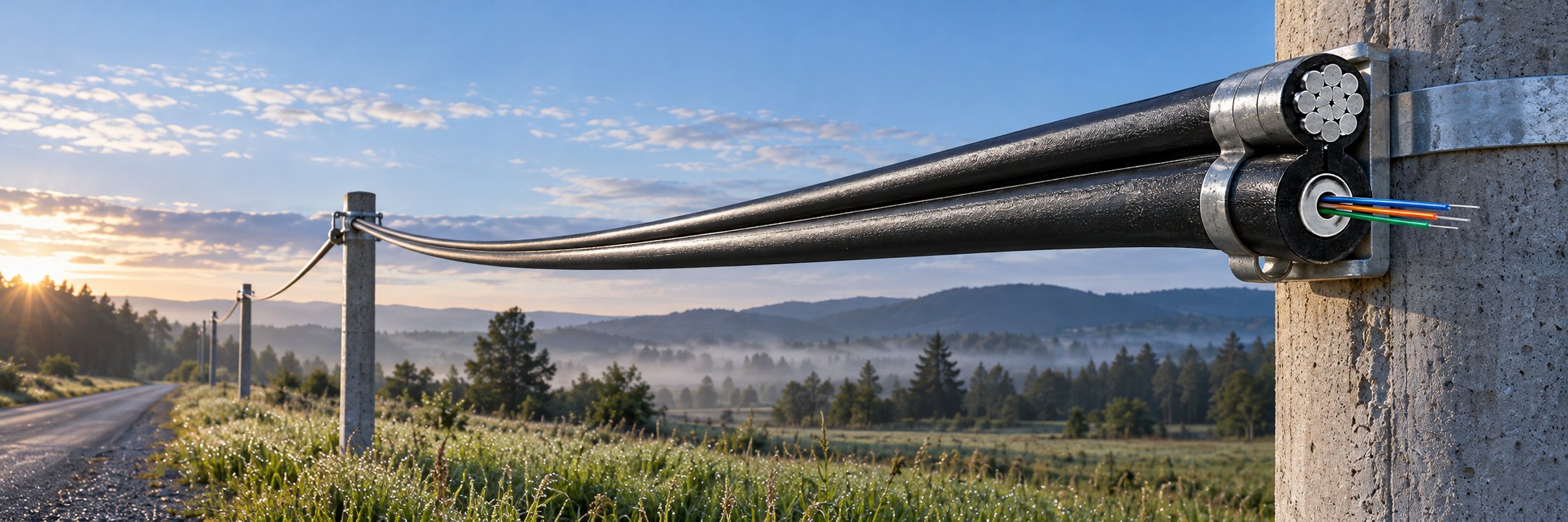
A buyer's guide to specifying and deploying Figure-8 self-supporting fiber optic cable on aerial spans: the loads that decide the messenger, steel strand versus FRP, fiber type and count, pole-line hardware and grounding, installation tension and sag control, acceptance testing, and the RFQ checklist for aerial distribution projects.
An aerial fiber route almost never fails because the fiber was the wrong grade. It fails because the span was built around the wrong load case, the messenger was sized by habit instead of by calculation, the installation tension was set by feel, or the crew needed two passes up the same pole line and lost the second half of the weather window. Buyers who have lived through one rework call-back normally start asking about span mechanics before they ask about unit price, and that is the right order of questions.
This guide is written for the people who actually place the order: network contractors, telecom distributors, ISP project buyers and OEM procurement teams sourcing aerial distribution cable for rural and urban access builds. It walks through what a Figure-8 self-supporting cable is, which loads decide the specification, how the messenger material changes the answer, how installation tension should be controlled on site, and what belongs in the request for quotation so that the reel that arrives is the reel your spans need.
Why aerial spans fail long before the fiber does
The optical core inside an aerial cable is usually the most reliable item on the pole line. What decides whether the route survives ten years of service is the mechanical system around it: the messenger, the clamps, the tension, and the sag the completed span settles at.
Every aerial span has to carry several loads at the same time, and they interact:
- Static load — the self-weight of the cable plus its integrated messenger, spread across the span.
- Wind load — aerodynamic drag on the cable diameter, which grows roughly with the square of wind speed and becomes much larger once ice has thickened the profile.
- Ice and snow load — a radial ice layer adds weight, adds diameter and therefore adds wind area at the same time.
- Thermal load — a steel messenger expands in summer heat and contracts in winter cold, so sag changes with temperature even with no wind and no ice.
- Vibration and fatigue — low-amplitude aeolian vibration works on clamps, dead-ends and the strand itself over thousands of cycles.
Two failure patterns follow directly from getting these loads wrong. The first is a clearance violation: sag grows beyond the design value, ground clearance or road crossing clearance shrinks, and the route has to be re-tensioned or re-routed after it has already been accepted. The second is mechanical damage to the cable itself: over-tensioning during stringing pulls the optical core into microbend loss, kinks form at sheaves or drums, and the loss only shows up at acceptance testing or, worse, months later.
There is also a commercial failure mode that buyers feel before any of the technical ones. A conventional aerial build needs two field operations: string the messenger wire first, then lash or clamp the cable to it. That second pass has its own truck roll, its own hardware, its own crew hours and its own risk of cable abrasion or misaligned clamps. On a long rural distribution route with wide pole spacing, the second pass is where the schedule slips. Reducing field operations is therefore not only a labour question; it removes a whole class of installation defects.
What a Figure-8 self-supporting cable actually is
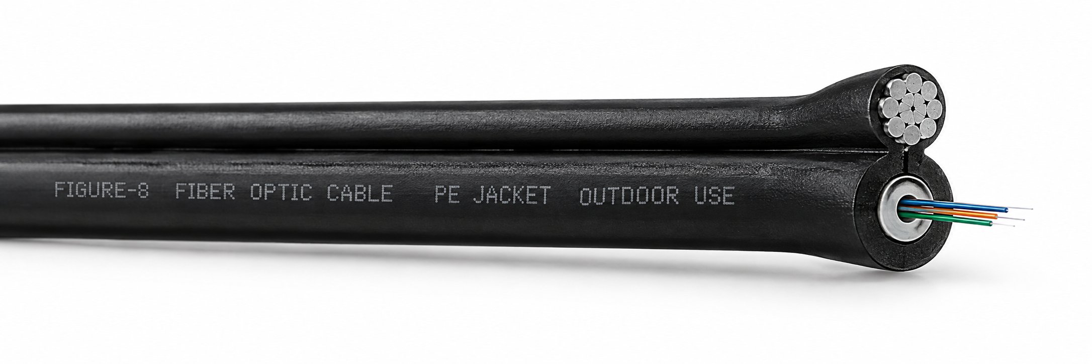
A Figure-8 self-supporting cable takes the two separate items of a lashed aerial build — the messenger and the optical cable — and bonds them into one cross-section at the factory. The profile looks like the number eight: one lobe carries the optical core, the other lobe carries the messenger, and a continuous jacket or web holds the two together along the full drum length.
The practical consequence is a defined load path. The messenger, not the optical core, carries the tensile load across the span, and the core sits in the second lobe essentially free of direct pulling stress. Because the two lobes are already attached, the crew pays out a single reel and installs the span in one pass. There is no separate messenger stringing operation, no lashing wire, no lashing machine and no suspension clamp that has to be positioned over a cable that is already hanging.
Typical industry values for the construction and the specification range are easy to state in general terms, but the exact figures always belong to the individual datasheet:
| Item | What is normally specified | Why the buyer cares |
|---|---|---|
| Optical core | G.652D single mode as the standard aerial grade | Matches mainstream ODN and FTTx transmission equipment; single-mode avoids mode-mixing questions on long distribution spans |
| Fiber count | Commonly 4 to 144 cores, customised to the network plan | Determines how much subscriber growth the span can absorb without a second build |
| Messenger | Steel strand or FRP (glass-fibre reinforced plastic) | Decides tensile capability, weight, lightning behaviour and corrosion exposure |
| Jacket | UV-resistant PE for outdoor aerial exposure | Controls ageing under sunlight, moisture and temperature cycling |
| Installation | Aerial, self-supporting over pole spans | Removes the separate messenger and lashing step |
| Application | Aerial spans in rural and urban distribution networks | The route class the design is intended for |
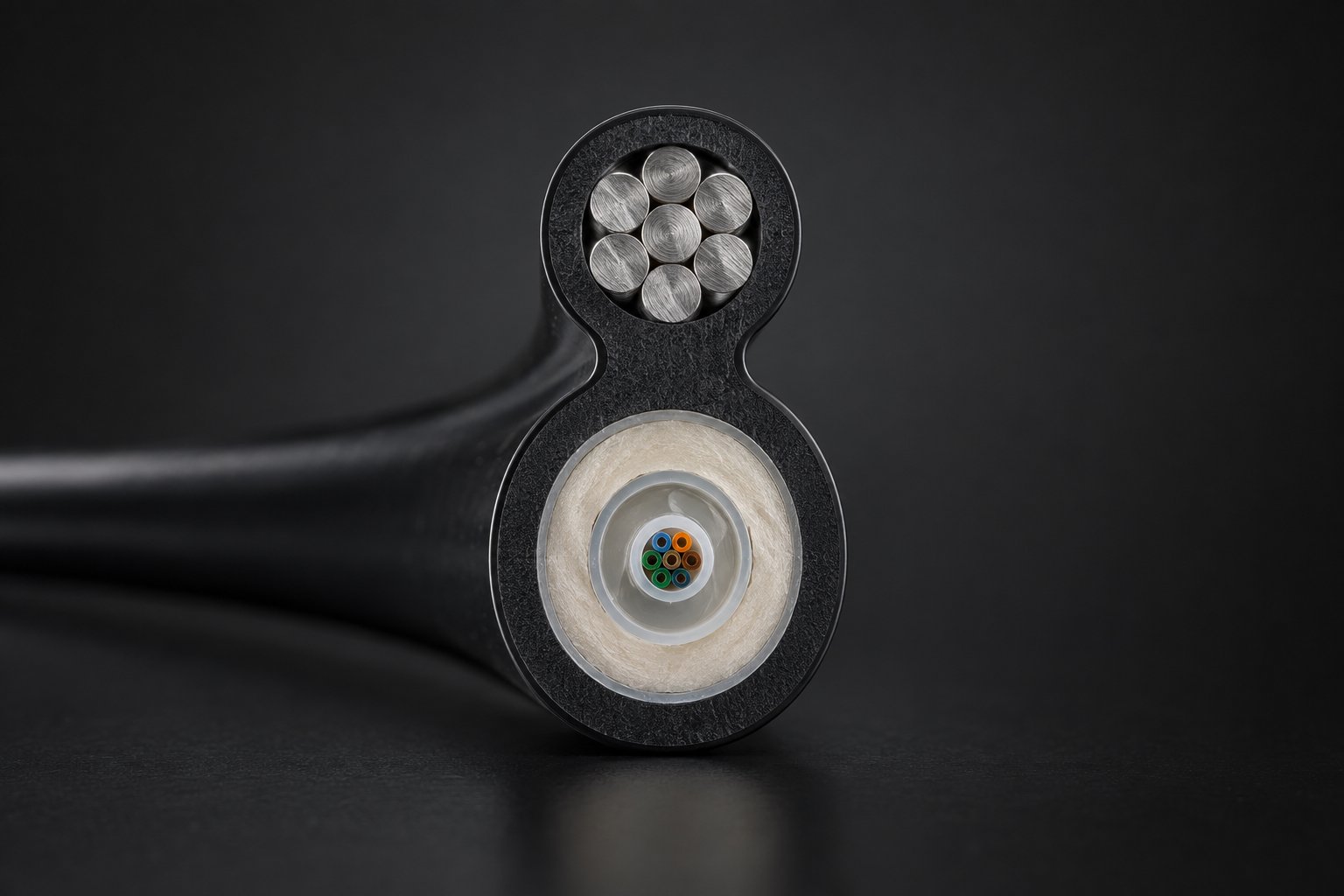
It is worth being equally clear about what a Figure-8 cable is not. It is not a substitute for span engineering: if the pole spacing, wind and ice loads or clearance requirements are wrong, the cable cannot rescue the design. It is not an all-dielectric product in the way ADSS is, because the standard version uses a metallic steel strand messenger, and that difference changes bonding, grounding and route selection. And it is not a composite ground-wire product: transmission-line designs such as OPGW belong to a different class of construction entirely and are specified separately from aerial distribution cable.
Nexora builds the Figure-8 self-supporting cable in Shenzhen as part of its fiber optic cable range, with G.652D single mode as standard, fiber counts from 4 to 144 cores as a customised configuration, a steel strand or FRP messenger and a UV-resistant PE jacket. The product page for the Figure-8 self-supporting cable lists the configuration options that can be quoted directly.
The four loads you have to quantify before you order
Buyers who send a supplier only a fiber count and a length usually end up in a second quotation round, because the messenger and the fiber count cannot be fixed without the span mechanics. Four inputs decide almost everything else.
1. Span length and pole spacing
The distance between attachment points sets the mechanical demand. A longer span increases both the load the messenger must carry and the sag it develops for a given tension, because sag rises with the square of the span. This is why rural routes with wide pole spacing and urban routes with dense poles can need different messenger configurations even when they carry the same fiber count.
2. Design wind speed
Wind load depends on the projected area of the cable and on the local design wind speed. Because the projected area includes any ice layer, wind and ice must be evaluated together, not as separate line items. Buyers working to a national or utility standard should quote that design wind speed in the RFQ; buyers working on a private network should at least state the region and the terrain type.
3. Ice and snow loading
In cold regions the radial ice thickness is often the governing load case, because ice adds weight and diameter simultaneously. A span that is comfortable in summer can be the one that fails clearance requirements after an ice storm, and the failure appears as a sag problem rather than a break.
4. Operating temperature range
The messenger expands and contracts with temperature. A steel messenger strung at a conservative tension on a cold morning can develop noticeably more sag on the hottest afternoon of the year. For FRP messengers the behaviour differs, and the datasheet should be consulted for the temperature range claimed for the specific construction.
How the messenger rating is used
Messenger selection is normally a comparison between the rated tensile strength of the strand and the maximum working tension allowed for the installation. Common field practice for distribution spans is to install at a working tension that is a modest fraction of the rated strength, so that wind, ice, creep and vibration all still have margin. As a general orientation, distribution aerial cable is often installed in the region of 15 to 25 percent of the messenger rated tensile strength, with the final figure confirmed against the datasheet and the local code. This is exactly the kind of number that must be treated as an industry reference rather than a guarantee: the exact permitted tension belongs to the cable datasheet you buy against, and to the pole-line design the route has to satisfy.
If the loading data is genuinely unknown at quotation stage, the honest approach is to say so and ask for the datasheet values of rated tensile strength, cable weight, minimum bend radius and installation tension limit, then return with the route data before the order is confirmed. A supplier who quotes a specific messenger grade without any span data is guessing on your behalf.
Steel strand or FRP messenger: how to decide
The messenger is the load-bearing member of a Figure-8 cable, so the material choice is the single most consequential specification decision on the product side. Both options are standard, and each one solves a different problem.
| Consideration | Steel strand messenger | FRP messenger |
|---|---|---|
| Tensile capability | Higher for the same nominal size; suits long spans and wider pole spacing | Generally lower than steel for an equivalent size; span capability has to be confirmed per project |
| Weight | Heavier, which affects handling and the load on poles | Lighter, easier handling and lower pole load |
| Lightning behaviour | Metallic member, so bonding and grounding become part of the pole-line design | Metal-free, which removes the conductive path and reduces induced-lightning exposure |
| Corrosion | Needs attention on coastal, high-salinity or chemically exposed routes | Not subject to galvanic corrosion of a metal strand |
| Typical fit | Long spans, high-tension distribution, conventional pole lines with established bonding practice | Lightning-prone areas, coastal salt routes, weight-sensitive poles and routes where a metal-free span is preferred |
The decision usually resolves into one of three situations. Where pole spacing is wide and the route crosses open terrain with little lightning activity, the higher tensile capability of steel strand is normally the deciding advantage. Where the route runs through a lightning-prone region, along a coast with high salt exposure, or on poles that are already heavily loaded, the metal-free FRP option often wins because it removes both the conductive path and weight. Where the route is mixed — some long crossings and some dense urban sections — the practical answer is usually to keep one messenger type for the whole order rather than to split configurations across a single drum sequence, unless the drum lengths are being planned separately anyway.
Two questions are worth asking the supplier before the messenger is frozen. First, what rated tensile strength and cable weight apply to the exact construction being quoted, since those are the numbers the span calculation runs on. Second, whether the quoted construction uses a steel strand or FRP messenger as standard, because the same nominal fiber count exists in both versions and they are not interchangeable on a span that has already been engineered. On routes where the messenger is metallic, the buyer should also confirm early who is responsible for bonding and grounding, since that is scope that sits between the cable supplier and the pole-line contractor.
Fiber type and fiber count for an aerial span
On aerial distribution spans, G.652D single mode is the usual standard because it matches the transmission equipment used in ODN and FTTx networks and because the distances involved do not require a more specialised fiber. Nexora's Figure-8 self-supporting cable is quoted with G.652D single mode as standard, with fiber counts from 4 to 144 cores as a customised configuration.
Sizing the fiber count is a planning exercise rather than a cable exercise, and the common mistake is to size to today's subscriber count. On an aerial distribution route, the expensive part of an upgrade is not the cable; it is the crew, the truck roll and the pole work. Buying headroom at order stage is therefore usually cheaper than returning to the route for a second cable. The method for choosing a count — current demand, growth forecast and redundancy, then a margin — is set out in more detail in the article on how to choose the right fiber count for a fiber optic cable order.
Two construction details interact with fiber count. First, higher counts produce a larger and heavier cable, which changes the messenger calculation — so fiber count and messenger choice cannot be finalised in isolation. Second, bend performance matters wherever the route turns corners at poles, enters closures or terminates in a distribution box; where tight routing space is expected, buyers sometimes specify a bend-improved single-mode fiber instead of standard G.652D, and that trade-off is described in the guide to bend-insensitive fiber for FTTH and indoor networks. For a straightforward aerial span with generous bend radii, standard G.652D is normally sufficient and is easier to source consistently.
Jacket, UV exposure and moisture protection
An aerial cable lives outdoors for its whole service life, so the outer jacket is doing real work rather than cosmetic duty. Nexora's Figure-8 construction uses a UV-resistant PE jacket intended for long-term outdoor aerial exposure.
The jacket has to resist three things at once. Ultraviolet radiation degrades polymers over years of exposure, which is why UV stabilisation matters more on aerial than on duct or burial cable. Temperature cycling between summer heat and winter cold causes expansion and contraction that the jacket and the web between the two lobes must tolerate without cracking. And moisture has to be kept away from the optical unit, which is handled by the water-blocking construction inside the cable rather than by the jacket alone.
The jacket cannot, however, seal the route. Every closure, every splice tray and every entry into a distribution box or ODF is a potential water path, and the most common long-term failure on an otherwise well-installed aerial span is moisture entering through an inadequately sealed termination rather than water penetrating the cable jacket. Buyers should treat closure sealing and entry sealing as part of the aerial scope and confirm who supplies and installs those components.
Where the route environment is aggressive — coastal salt spray, industrial atmospheres, agricultural dust, strong sustained wind — it is worth stating that environment in the RFQ. It does not change the fiber, but it influences jacket material confirmation, hardware selection and the maintenance interval the operator should plan for.
Pole-line hardware, anchoring and grounding
The cable is only one member of the completed span. The hardware package decides whether the installed route behaves the way the design predicted.
At each end of a span, the messenger is gripped by a dead-end or anchoring assembly that transfers the span load into the pole. At intermediate poles, the cable is supported by a suspension clamp that holds the profile without crushing the optical lobe. Corners and changes of direction need their own treatment, because the resultant load at an angle pole is larger than the load on a straight-through pole, and pole guying may be required. None of this hardware is unusual, but the buyer needs to know whether it is in the cable supplier's scope or the contractor's scope, and whether the clamps offered are designed for the specific profile and messenger of the cable being supplied.
Minimum bend radius is the constraint that most often gets violated in the field. It applies at every sheave, every pole, every corner and every point where the cable enters a closure or a box. The exact minimum bend radius for a given construction belongs to the datasheet; the field rule is simply that the radius is never made tighter for convenience, and that the cable is not pulled around a sharp pole edge because a guide roller was not available.
Bonding and grounding depend on the messenger material. With a steel strand messenger, the route includes a conductive member that has to be bonded according to the applicable practice, and the pole-line design should account for it from the start rather than as a field improvisation. With an FRP messenger, the metal-free construction removes that requirement. This is one of the reasons the messenger decision cannot be made purely on tensile strength: it also selects a different electrical and grounding scope.
Separation from power conductors and the choice of route class are design responsibilities, but they interact with the cable choice. On routes that run in high-voltage corridors or where the pole line is shared with power distribution, the all-dielectric ADSS option is often the more natural fit than a cable with a metallic messenger, and the trade-offs are covered in the article on whether ADSS cable is the right choice for an aerial network. Buyers comparing the two should look at the ADSS fiber optic cable page alongside the Figure-8 page, because the two products answer different route conditions rather than competing on price alone.
How installation tension is controlled on site
Tension control is where a technically correct specification either becomes a working route or a callback. The principle is simple: the messenger carries the load, but the tension it is pulled to determines the sag of the finished span, and both over-tensioning and under-tensioning create problems.
Over-tensioning is the more damaging of the two. Pulling harder than the installation tension limit raises stress in the strand and in the cable web, increases the risk of microbend loss in the optical core, and increases the load transferred into every pole and anchor. Under-tensioning looks harmless but leaves excessive sag, which reduces clearance and increases the aerodynamic movement of the span in wind.
The relationship between tension and sag
For an installed span, tension and sag are linked by the approximate catenary relationship:
where w is the cable weight per unit length, L is the span length and T is the horizontal tension.
Two consequences follow that buyers should carry into the field discussion. Sag rises with the square of the span, so doubling the span roughly quadruples the sag at the same tension. And sag falls in inverse proportion to tension, so a modest increase in tension produces a large reduction in sag — which is exactly why tension has to be measured rather than estimated by eye.
A worked example, for orientation only
Take a 60 m span with a combined cable and messenger weight in the region of 2 N per metre, and an installation tension of about 1.2 kN. The approximate sag is (2 × 60²) ÷ (8 × 1200) = 7200 ÷ 9600 = about 0.75 m, or roughly 1.2 percent of the span. That value sits in the range normally considered reasonable for an aerial distribution span, and it illustrates why the figures must be checked against the real datasheet values rather than assumed: if the same span carried a heavier construction, the sag at identical tension would be proportionally larger.
These numbers are given as an orientation example using typical values, not as a specification. The rated tensile strength, cable weight and permitted installation tension for the cable you buy are the figures that govern, and the exact values must be taken from the datasheet.
Field methods for getting tension right
- Measured tension stringing. The cable is pulled with a dynamometer or tension-controlled winch, so the tension at the pulling end is read continuously and held at or below the limit stated for the cable. This is the most direct method and is the one to require on long or critical spans.
- Sag measurement by observation. The crew observes the low point of the span against sight boards set to the calculated sag for the expected conductor temperature. It is simple and needs no instrumentation beyond a sighting target, but it depends on a correctly calculated target and on reasonable temperature assumptions.
- Oscillation timing. The span is displaced and released, and the period of oscillation is timed to derive tension from the physical relationship between period, weight and span. Useful as a cross-check when a tension reading is disputed.
- Final sag check after creep. Steel strands creep under sustained load, and the messenger settles. A completed route often needs a re-check of sag after a settling period, and the acceptance criteria should say who performs that check and against which value.
The installation mistakes that cost the most
- Pulling at full winch speed without respecting the bend radius at sheaves and drum exits, which is how kinks and local loss are created.
- Leaving the cable on the ground or dragging it across abrasion points during stringing instead of using rollers and guide shoes.
- Using the optical lobe as a pulling eye, which loads the core directly instead of the messenger.
- Skipping service loops at poles and at entries, so later re-splicing or re-termination has no spare length to work with.
- Failing to record tension, sag and temperature at installation, which removes the baseline for every future comparison.
Figure-8, ADSS or lashed cable: how to choose
Three aerial approaches cover most distribution builds, and the right answer depends on the route rather than on the brand.
| Approach | How it is installed | Strongest fit | Watch points |
|---|---|---|---|
| Figure-8 self-supporting cable | One pass; messenger is integral to the cable profile | Pole-dense rural and urban distribution where installation passes and labour cost decide the schedule | Span must be engineered; steel strand version brings bonding and grounding into scope |
| ADSS all-dielectric cable | One pass; span load carried by an aramid-reinforced all-dielectric construction | Routes where a metal-free span is required, including power corridor routes and lightning-prone areas | Requires its own span and hardware engineering; not a drop-in substitute for a messenger-based design |
| Lashed aerial cable | Two passes; messenger strung first, then cable lashed to it | Routes where existing messenger is already in place, or where cable must be added to a mature pole line | More field operations, more hardware, more abrasion risk during the second pass |
The practical decision rule is straightforward. If the route is a new aerial build and the pole line is being designed together with the cable, a self-supporting design that removes a field operation is usually the better commercial answer. If the route follows a power line, or the all-dielectric property is a hard requirement, ADSS is the correct family. If a messenger is already installed and only the cable has to be added, lashing the new cable to the existing messenger may be the only sensible option, even though it costs a second pass.
It is worth noting that the choice also changes the spare parts and the skills the operator needs in the field. A contractor who installs a lot of lashed aerial cable already owns lashing equipment; a contractor moving to Figure-8 cable needs different clamps and different drum handling practice, and that change is worth planning one project ahead rather than discovering on site.
Splicing, terminations and the ODF end of the span
The aerial span ends at a splice closure, a distribution box or an ODF, and that transition is where installation quality is most visible later. Three details deserve attention at the ordering and design stage.
First, slack. Both ends of the aerial segment should have enough cable and enough service loop at the nearest pole to allow a future re-splice. Cutting a span tight to save cable is a false economy; the cost of a re-splice without slack usually exceeds the cost of the metre that was saved.
Second, the entry into the box or frame. Cable entering a distribution box or an ODF should be secured before it reaches the tray, so that the span tension is not transferred into the tray or the fibre management area. This is the point where a bend radius violation produces immediate loss, and the fibre inside the frame usually has to be ordered separately: the article on how to specify a fiber optic pigtail for ODF, FTTH and data center networks explains how the pigtail side of the terminations is normally specified alongside the cable.
Third, sealing and labelling. Every closure, entry port and gland should be sealed against moisture, and every span should be labelled at both ends with the route identity and the fiber count so that future fault location starts from documentation instead of guesswork. On a long aerial route, span labelling is cheap at installation and expensive to reconstruct two years later.
Acceptance testing after the last span is clamped
Installation is not complete when the last clamp is fitted; it is complete when the route has been tested and the results have been recorded against a baseline.
Inspection first: check that bend radii have been respected at every pole and corner, that service loops exist where they were planned, that dead-ends and suspension clamps are seated correctly, that no span shows visible damage or abrasion, and that no sag is obviously out of line with the calculated value for the temperature at the time of the check.
Then optical testing. Continuity and insertion loss on the completed route confirm that no span was damaged during stringing. An optical time domain reflectometer trace taken at completion becomes the reference for every future comparison, because a cable that has been installed and accepted without a baseline cannot be diagnosed later without argument about whether a loss was always there. The method and the trace-interpretation pitfalls are described in the guide to using an OTDR to accept a new fiber optic cable installation.
Finally, compare measured loss against the design allowance. The link loss budget the route was designed to is what the acceptance figures should be checked against, and the calculation method is set out in the article on how to calculate a fiber optic link loss budget. Keeping the installation record — tension, sag, temperature, test results, dates — turns a completed span into documented evidence, and that documentation is what a warranty discussion is actually based on.
What to put in a Figure-8 cable RFQ
A well-prepared RFQ shortens the quotation cycle and removes the most common source of mismatched reels. The list below is the minimum set of information a manufacturer needs to quote a span-verified construction rather than a generic one.
| RFQ item | Example of what to state |
|---|---|
| Application and route class | Aerial self-supporting distribution, rural and urban pole line |
| Span length and pole spacing | Longest span, typical span, angle poles |
| Environmental loads | Design wind speed, radial ice thickness, operating temperature range |
| Fiber type | G.652D single mode standard, or a bend-improved single-mode grade if tight routing is expected |
| Fiber count | Current requirement plus growth margin, for example a count inside the 4 to 144 core custom range |
| Messenger | Steel strand or FRP, with the reason stated (span length, lightning, corrosion, weight) |
| Jacket and environment | UV-resistant PE, plus coastal, industrial or agricultural exposure notes |
| Drum length and markings | Length per drum, drum sequence, span marking or print legend requirements |
| Tests and documentation | Which test reports are required with the shipment, and in what language |
| Hardware scope | Whether clamps, dead-ends and closures are part of the supply or supplied separately |
| Commercial terms | Quantity, delivery destination, packaging, invoice currency, required delivery window |
| Warranty expectation | Standard terms: 12 months from shipment date |
Two commercial items cause most of the back-and-forth. The first is quantity and MOQ: cable is quoted per drum and per kilometre, and the achievable price depends on the drum configuration and the total length, so stating the total route length in kilometres and the number of drums wanted removes an entire round of questions. Typical MOQ and lead-time ranges for fiber optic cable and patch cords from a manufacturer are summarised in the article on MOQ and lead time when ordering from a manufacturer, and the exact figures for a specific Figure-8 configuration should be confirmed with the supplier at quotation.
The second is warranty. Nexora's standard terms for this product are 12 months from shipment date, and that wording matters because it defines the start of the period as shipment rather than installation, which is important on projects where the cable is stored on site before the crew arrives. How that period is normally interpreted for fiber optic buyers is explained in the article on what a 12-month warranty really covers. A full RFQ checklist for fiber optic purchases in general is available in the guide to what to include in a fiber optic cable RFQ.
Comparing one-pass and two-pass aerial builds
Price per metre is the easiest number to compare and the least useful one on an aerial build. The cost of an installed span is the cable plus the hardware plus the crew hours plus the cost of correcting defects, and a self-supporting design changes three of those four items.
| Cost element | Self-supporting Figure-8 build | Separate messenger plus lashed cable |
|---|---|---|
| Field passes along the pole line | One | Two |
| Support structure | Integral messenger in the cable profile | Separate messenger wire plus lashing wire or clamps |
| Hardware items | Dead-ends and suspension clamps for one profile | Messenger hardware plus lashing or clamping hardware for the cable |
| Installation risk | One stringing operation to control | Second operation creates abrasion and alignment risk on an already-hung cable |
| Schedule exposure | Lower: fewer operations to fit into the weather window | Higher: the second pass is the one that slips |
| Where the saving shows | Multiplies across every span on the route | Only favourable where a messenger is already installed |
The arithmetic favours the self-supporting design as the number of spans grows, because the saving is per span rather than per metre. On a short route with a handful of poles the difference may be marginal and may be outweighed by the contractor's existing lashing equipment and habits. On a rural distribution route with hundreds of spans and wide pole spacing, the labour difference usually dominates the material difference, and the reduction in rework risk is an additional, harder-to-price advantage.
Where a messenger is already installed and paid for, the comparison changes completely: lashing new cable to existing infrastructure avoids new messenger material and new pole loading analysis, and that can outweigh the cost of the second pass. The honest answer for a mixed estate is to treat new-build spans and rebuild spans as separate procurement decisions instead of forcing one cable type across both.
Choosing a supplier for aerial cable projects
Aerial cable is usually bought in repeat orders against long projects, so the supplier's ability to keep a configuration stable matters as much as the first quotation.
Nexora Communications is a Shenzhen-based manufacturer of fiber optic network equipment founded in 2014, with a 16,000+ m² manufacturing facility, 180+ employees, 12 production lines and an annual capacity of 2.8M+ units. Production covers more than 3,500 product configurations, and quality control runs through incoming material, component, in-process, functional, visual, final and packaging inspection across 30+ QC stations. More than 500 OEM/ODM projects have been delivered for customers in 50+ countries and regions.
For an aerial cable order, those capabilities translate into four questions worth asking before the purchase order:
- Configuration stability. Can the exact construction quoted — fiber type, count, messenger material, jacket — be repeated consistently on reorders, and is the same construction documented in the datasheet supplied with the quotation?
- Inspection scope. Which inspections are performed on this cable before packing, who performs them, and which records accompany the shipment?
- Customisation limits. Whether a specific fiber count, drum length, print legend or messenger configuration is available as an OEM/ODM configuration, and what that does to lead time.
- Documentation and support. Whether the datasheet, drum schedule and inspection records are supplied in the buyer's working language, so the installation crew and the accepting engineer work from the same document.
Buyers sourcing other outdoor cable types for the same project can review the outdoor G.652D single mode fiber optic cable and the armored fiber optic cable options alongside the Figure-8 range, since duct, burial and aerial segments of the same network are frequently ordered together and can share a drum schedule.
Buyer FAQ
What makes a Figure-8 cable self-supporting?
The messenger is bonded to the optical cable at the factory, so the two are pulled as one unit and the messenger carries the span load. There is no separate messenger stringing operation and no lashing step. The optical core sits in its own lobe and is not loaded directly.
How do I choose between a steel strand and an FRP messenger?
Compare span length, wind and ice loading, lightning activity and corrosion exposure. Steel strand offers higher tensile capability for long spans and wide pole spacing; FRP is lighter and metal-free, which suits lightning-prone, coastal and weight-sensitive routes. The achievable span for either option must be confirmed against the datasheet for the exact construction.
What fiber counts are available?
Nexora's Figure-8 self-supporting cable is quoted from 4 to 144 cores as a customised configuration, with G.652D single mode as standard. Size the count to current demand plus growth margin, since returning to an aerial route for a second cable costs far more than the cable itself.
Can I install a Figure-8 cable on existing poles?
Yes, provided the pole line is checked for the added load and the hardware matches the cable profile. Where a messenger is already installed and engineered, adding cable to it by lashing may be the simpler route; where the pole line is being built or rebuilt, the single-pass self-supporting approach usually reduces field work.
What tension should the crew pull to?
Never more than the installation tension limit stated for the cable. Distribution aerial spans are commonly installed at a modest fraction of the messenger's rated tensile strength, with the exact figure taken from the datasheet and the pole-line design. Tension should be measured with a dynamometer or verified by sag measurement, not estimated by eye.
How much sag is acceptable?
Sag is a design output, not a fixed number: it follows from span length, cable weight and installed tension, and it increases with temperature. The acceptance value comes from the span calculation for the route and the clearance rules that apply. Recording the sag and the temperature at installation gives you the baseline for later checks.
Is the jacket suitable for long-term outdoor exposure?
The construction uses a UV-resistant PE jacket intended for long-term outdoor aerial exposure. Closures, entry ports and terminations still need proper sealing, because moisture usually enters a route through a termination rather than through the jacket.
Does a Figure-8 cable replace the need for a span calculation?
No. The cable carries the load the design gives it; it does not correct a span that is too long, a pole spacing that exceeds the design case, or a clearance requirement that was never checked. Supply the loading data with the RFQ so the messenger and span can be matched.
What is the minimum bend radius in the field?
The datasheet value for the specific construction governs. In practice, the controlling points are sheaves during stringing, pole edges and corners, and the entry into closures, boxes or frames. Bend radius violations are the most common cause of avoidable loss on an aerial span.
What warranty applies?
Nexora's standard terms are 12 months from shipment date. That wording defines the start of the period as the shipment date rather than the installation date, which is relevant on projects where cable is stored on site before installation.
Which tests come with the cable?
Quality control covers incoming material, in-process, functional, visual, final and packaging inspection through 30+ QC stations. The specific test items and the records supplied with a particular order should be confirmed at quotation, because the required documentation varies by project and by destination market.
Request a quotation
To quote a Figure-8 self-supporting cable that matches your spans rather than a generic construction, send the span length and pole spacing, the design wind and ice conditions, the operating temperature range, the required fiber type and count, the messenger preference, the jacket and environmental requirements, and the total route length in kilometres with the drum schedule you want. If any of those values are still open, say so — the datasheet figures for rated tensile strength, cable weight, installation tension and minimum bend radius can be confirmed first, and the configuration can be finalised once the route data is available.
Typical values quoted in this guide are industry references for orientation. The governing figures for any order are the ones on the datasheet of the construction you buy, and they should be confirmed in writing before the order is placed.