
How long fiber optic cable really lasts: what ages and what does not, typical service life by cable type and environment, early warning signs, repair versus replace decisions, and how to plan replacement budgets.
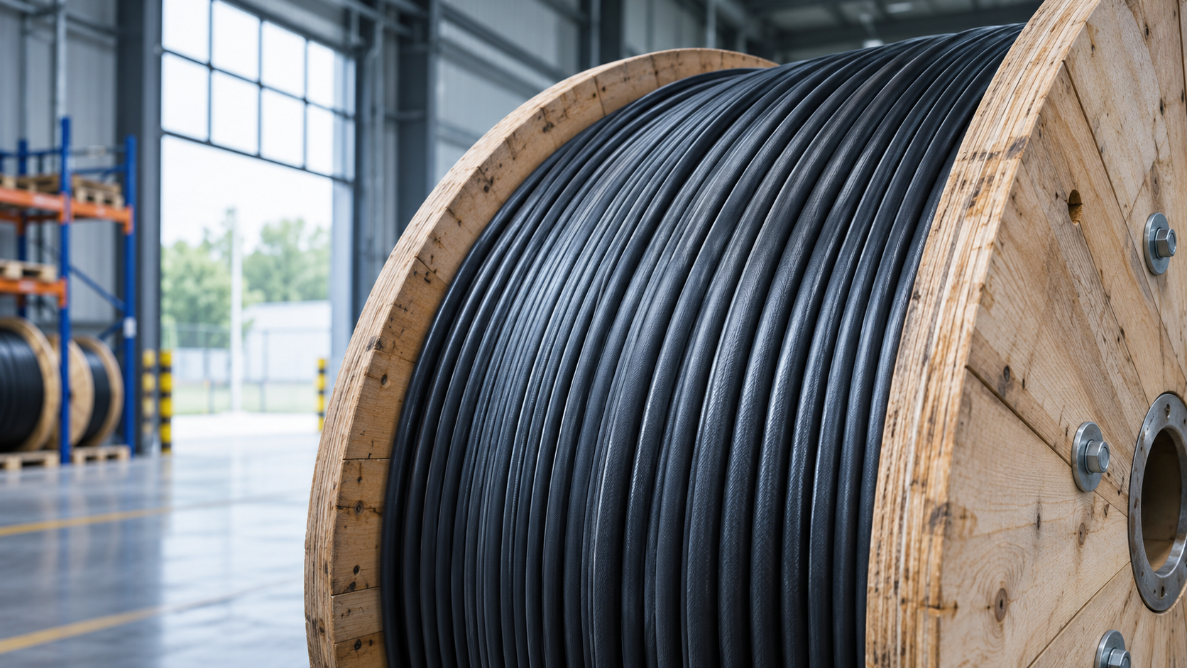
Why the Service Life Question Decides Your Procurement Economics
Ask any network owner what a kilometre of fiber optic cable actually costs and you will usually get a number. Ask what it costs per year of service, and the room goes quiet. That second number is the one that matters, because it is the only honest way to compare a cheap cable that needs re-sectioning every five years against a properly specified build that runs for two decades with nothing more than routine maintenance. When you are signing off procurement for a metropolitan ring, an FTTH footprint or an industrial campus backbone, the expected service life is not a technical curiosity — it is the denominator of your entire cost model.
B2B buyers ask us about longevity for three practical reasons. First, financing: networks are funded against multi-year depreciation schedules, and a cable that ages faster than the depreciation curve turns an asset into a liability. Second, tender language: operators increasingly require suppliers to state design life and material grades explicitly, which means you need to know what those statements actually rest on. Third, failure history: if your previous build suffered water ingress, rodent damage or jacket cracking, the next purchase order is written by that experience. None of these questions can be answered with a generic "25 years" figure, because the honest answer depends on the cable construction, the environment and — more than anything else — the installation.
This article walks through the whole picture. We start with what actually degrades a fiber cable: the silica glass itself, the polymer and metal components around it, and the installation practices that set the starting condition of every core. From there we move to condition monitoring — how to use OTDR baselines and periodic testing to detect aging before it becomes an outage — and then to the harder judgement call of when to repair versus when to replace a section or an entire route. We close with replacement budgeting: how to build cable renewal into multi-year capex planning so that a 2030 upgrade does not ambush a budget written in 2026.
One note before we begin. Service life claims are only as credible as the factory behind them. A cable is a 20-year decision, but many suppliers will not be in business — or will not honour documentation — for that long. If you are still shortlisting vendors, it is worth reading our guide to choosing a reliable fiber optic cable manufacturer for long-term B2B supply before you commit, and to reading a fiber optic cable datasheet before you buy so you can compare material grades like for like rather than price for price.
What Actually Determines Fiber Optic Cable Service Life
"How long does fiber cable last?" sounds like a single question, but it hides at least three separate ones: how long does the fiber itself last, how long does the cable structure last, and how long does the installation hold up. A cable is a system, and its service life is the shortest of those three clocks — not the longest. A route with pristine glass inside a waterlogged sheath is a failing route. Understanding each clock separately is what lets you predict problems and budget realistically.
The Glass Is Rarely the Weak Point
Start with the part everyone worries about first: the fiber. Modern silica single-mode fiber is remarkably durable. Under normal strain — essentially zero once the cable is correctly installed and the fiber is slack within the loose tube — the glass does not meaningfully attenuate with age. A new G.652D fiber shows attenuation of 0.36 dB/km or better at 1310 nm and 0.22 dB/km or better at 1550 nm (typical values, subject to the datasheet). On a healthy route, those numbers are essentially the same after ten years as they were on day one, which is why OTDR trend comparison over time is such a powerful diagnostic: change means damage, not aging glass.
The genuine fiber-level aging mechanism is static fatigue, driven by the microscopic surface flaws every fiber carries. When fiber is held under sustained tensile stress — through over-tensioned pulling, tight coiling, or a closure that clamps the fiber rather than the tube — those flaws grow slowly, and the fiber eventually breaks, sometimes years after the triggering event. The stress is almost never intentional; it is the residue of a rushed install. This is why we tell buyers that fiber lifetime is largely set on installation day, not in the factory. The proof-test every fiber undergoes at manufacture (commonly screened at around 1% strain, typical value — confirm on the datasheet) gives you a flaw-free margin, but only if nobody spends that margin afterwards.
There is also hydrogen darkening, where hydrogen diffusing into the glass raises attenuation at specific wavelengths. It matters mainly in poorly water-blocked cables sitting in wet environments or in older designs with hydrogen-generating materials. The practical takeaway is the same: keep water out of the cable and keep the fiber unstressed, and the glass will outlast every other component of your network, including the electronics at either end.
The Cable Around the Fiber Is
In our field experience, the cable structure — not the glass — is what limits real-world service life. Each component ages on its own schedule, and the failure usually starts with water.
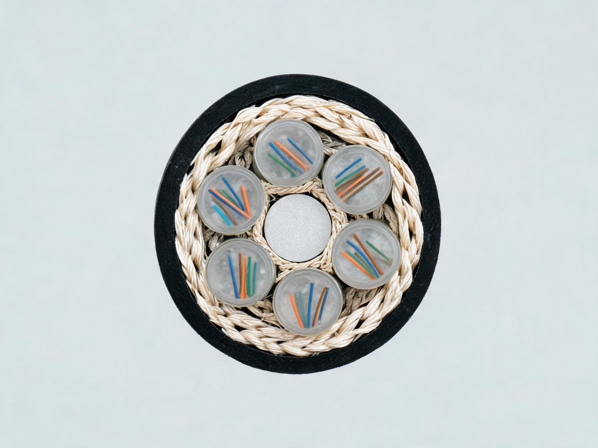
The jacket comes first. Outdoor cables use black HDPE precisely because carbon black gives strong UV resistance; a well-specified PE jacket in a duct or direct-buried environment typically holds its mechanical properties for many years. But jacket life drops sharply when the cable is exposed to conditions it was not designed for: continuous direct sunlight on an indoor-rated jacket, sustained contact with hot duct surfaces, hydrocarbon-contaminated soil, or rodent attack that breaches the sheath and opens a water path. A small jacket breach is rarely an immediate outage — it is a slow entry point for water that migrates along the cable until it reaches a splice closure, which is when the fault appears, often several kilometres from the actual hole.
Then the water-blocking system. Gel-filled loose tubes and water-swellable tapes or yarns are the primary defence, and their job is to stop longitudinal water migration if the sheath is ever breached. Gel itself is chemically stable for decades at normal operating temperatures — outdoor builds are typically rated from -40 °C to +70 °C, typical value, subject to the datasheet — but repeated thermal cycling can pump moisture past degraded closure seals, and swellable materials have a finite absorption capacity. Once water sits against fiber for years, microbending and eventually hydrogen effects begin to show up in OTDR traces.
Armor and strength members age differently. Steel tape or steel wire armor on a direct-buried cable essentially lasts as long as its jacket protects it from corrosion; a punctured jacket lets soil moisture reach the armor and corrosion works inward. Steel wire or FRP strength members rarely fail on their own — they fail because something else compromised the cable. The practical implication for buyers: specify the armor and water-blocking system for the actual environment, not a generic one. Our guide to choosing fiber optic cable for harsh environments covers temperature, water-blocking and UV considerations in detail, and where rodent pressure or rocky trenching is expected, armored construction earns its cost premium many times over. If your route includes high-risk sections, it is worth reviewing the armored fiber optic cable range rather than accepting one jacket type for the whole project, and understanding how armored builds are constructed so you can inspect samples before acceptance.
Finally, note that aging is uneven along a route. The 500 m of cable in a flooded manhole ages far faster than the 4 km on a dry hillside. Condition-based replacement planning (later in this article) beats calendar-based planning precisely because of this unevenness.
Installation Quality Decides the Baseline
Every cable leaves the factory with a designed service life. Installation decides how much of it you actually get. Three installation variables dominate.
The first is pulling tension. Exceeding the cable's rated maximum pulling force — or worse, pulling directly on the fiber rather than the strength member — stretches the cable, strains the fiber inside the loose tube, and embeds a permanent latent defect. Strained fiber does not usually fail immediately; it fails at year three or year eight through static fatigue. Insisting on proper lubrication, intermediate pull points on long runs, and tension-monitored winches is the cheapest service-life extension you can buy. Our contractor's guide to pulling fiber optic cable without exceeding tension and bend limits walks through the practical controls.
The second is bend radius. During installation, the minimum bend radius is typically 15–20 times the cable outer diameter, relaxing to 10–15 times OD in service (typical values, subject to the datasheet). Violate this in a manhole corner, a slack loop or a crowded tray, and you create macrobending loss — visible immediately at 1550 nm before it is visible at 1310 nm — plus, if the cable is pinched or kinked, a long-term stress point on the glass. The bend that survives commissioning but breaks in year five is a classic pattern, and it is nearly always traceable to a tight coil in a closure or a sharp duct transition.
The third is closure and slack management. Splice closures are the most serviced, most environmentally exposed points on any route, and their seals are what keep water out of the cable system over decades. Poor slack storage — fiber coiled too tightly, tubes kinked where they enter the closure, trays overcrowded — creates exactly the sustained micro-stresses that shorten fiber life. Getting closure selection and slack-loop practice right at installation is far cheaper than re-opening closures for years afterwards, and our guide to choosing a splice closure and managing slack storage covers the specification details.
Buried routes add a fourth variable: backfill and depth. Cable laid on sharp rock with no bedding, or at shallow depth in ground that later gets excavated by third parties, accumulates mechanical damage that no datasheet can predict. Following correct direct-buried installation practice — trench bedding, depth, warning tape and duct transitions — sets a starting condition the cable can actually defend for its full design life. When installation is controlled, the factory-designed life of the cable is what you get; when it is not, you inherit a lifespan nobody can promise.
How Each Cable Component Ages Over Time
When buyers ask "how long will this cable last," the honest answer is that a cable is not one material but a stack of them: polymer jacket, water-blocking gel, tubes, strength members, armor and, at the ends of the link, connectors and closures. Each element ages on its own clock, and the network's real service life is set by whichever one gives out first. Understanding where each component is weak tells you what to inspect, what to specify more conservatively, and when a failure is a repair job versus a section replacement.
PE Jackets: UV, Moisture and Mechanical Wear
The black HDPE jacket is the cable's first and most important line of defence, and it is also the component most exposed to the environment. High-quality black PE compounds incorporate carbon black, which blocks ultraviolet radiation effectively; that is why outdoor jackets are black rather than coloured. In practice, a well-formulated jacket on an aerial or duct cable shows little measurable UV degradation for many years, but cheaper or recycled compounds can chalk, crack and lose elongation within a handful of seasons. When you evaluate suppliers, ask specifically about the jacket material grade rather than accepting "PE" as a specification.
Moisture is the quieter enemy. PE is not a perfect water barrier; over decades, water vapour diffuses through the jacket, which is why water-blocking elements inside the cable matter even in duct installations. Mechanical wear is more visible: rodent gnawing on buried routes, abrasion where a duct cable rides over a duct edge, and abrasion at every point where an aerial cable contacts a support hardware. On your inspection rounds, look for localised jacket damage rather than uniform aging — a single chafe point can admit water and start a failure that spreads along the cable.
Temperature cycling also works on the jacket. Outdoor builds are rated for a typical operating range of -40 °C to +70 °C (typical value, subject to the datasheet), but repeated expansion and contraction stiffens the polymer over time and can open small cracks at points of constant flex, such as where cable enters a closure or crosses a road in an aerial span. If your route sits in a hot climate with strong solar loading, jacket thermal aging will generally be the first limiting factor, not the glass.
Water-Blocking Systems and Gel
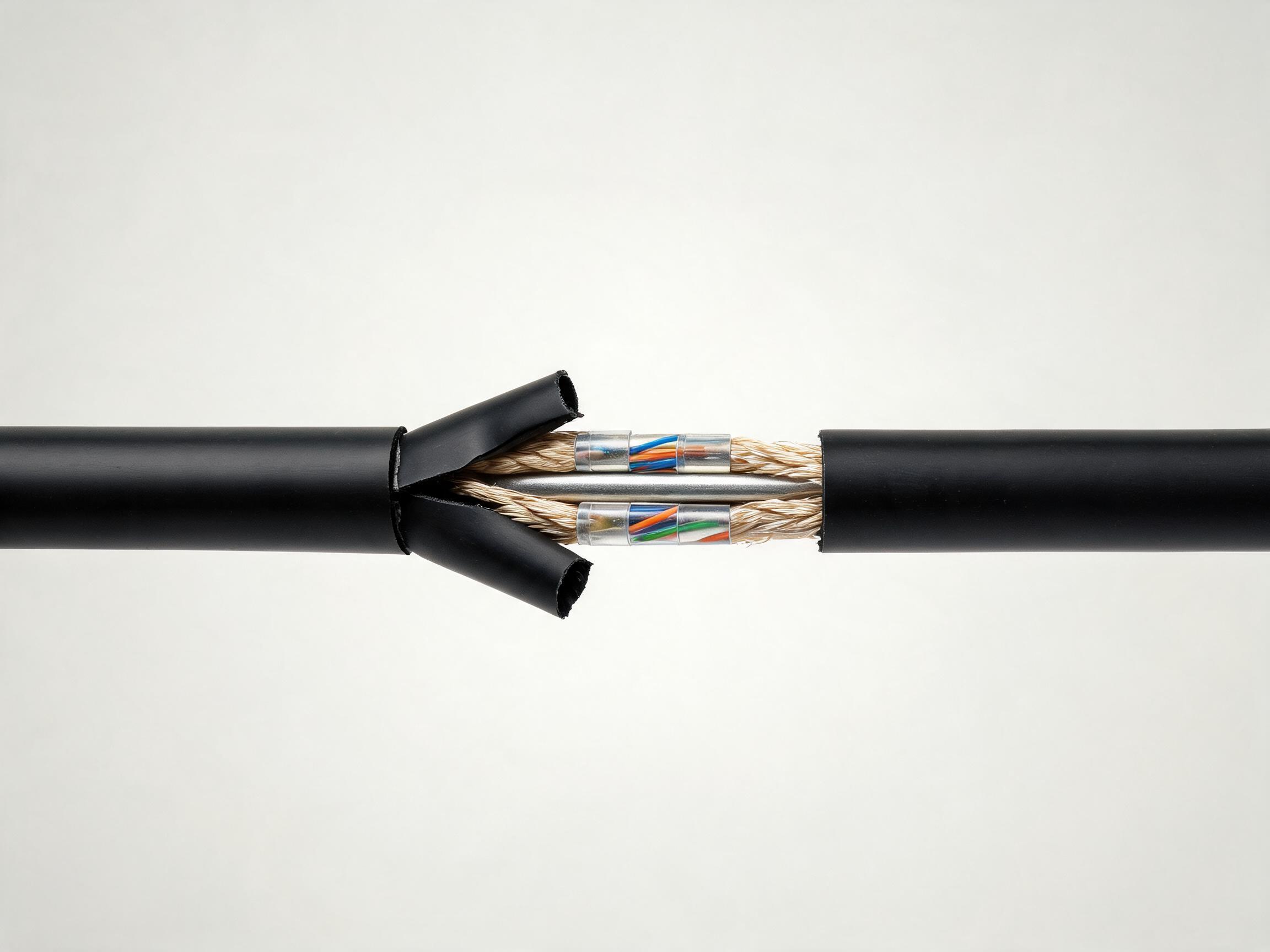
Inside a loose-tube outdoor cable, the interstices of each tube are filled with thixotropic gel, and water-blocking yarns or tapes run along the cable core. The glass itself is almost unaffected by water in any timescale that matters for network planning; what water attacks is everything around the glass. If water reaches the fibre surface through a breached tube, stress corrosion can initiate microcracks that grow under residual bending stress, eventually causing attenuation steps and, in the worst case, breakage at a bend point.
Gel ages in three ways worth knowing about. First, it can bleed or separate if the cable is stored for years in high temperature — one more reason to rotate warehouse stock and follow proper warehouse cable storage practice on reels rather than leaving drums in the sun. Second, gel can be washed out mechanically at any point where the jacket is breached, letting water wick along the tube. Third, in cables that rely on dry water-blocking tapes instead of gel, the superabsorbent material has a finite swelling capacity; once it has absorbed what it can at a breach point, continued water ingress defeats it.
For the buyer, this means the water-blocking specification deserves as much attention as attenuation. When comparing offers for harsh or wet routes, check how the cable achieves water blocking — gel-filled tubes, water-swellable tapes, or both — and confirm the longitudinal water penetration test conditions on the datasheet. Our guide to choosing cable for harsh environments covers how to weigh these options against route conditions. In the field, a sudden attenuation increase at a specific point, combined with evidence of jacket damage, is a strong indicator that water has entered the core and that section replacement deserves consideration over splicing alone.
Strength Members and Armor
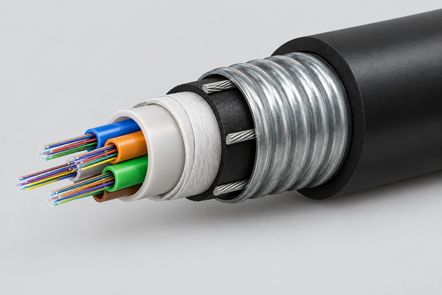
The strength member — central steel wire or FRP in a loose-tube cable — and any armor layer are the longest-lived parts of the assembly, provided they were never overloaded during installation. Steel does not corrode while it is sealed inside the jacket and water-blocking system; corrosion becomes possible only after mechanical damage exposes the member. FRP is immune to corrosion entirely, which is why all-dielectric builds suit routes with lightning exposure or inductive interference, and why the choice between steel and FRP is as much a siting decision as a mechanical one.
Armor deserves its own inspection logic. Steel tape armor under a PE oversheath protects against rodents and crushing on direct-buried routes; steel wire armor handles higher tensile loads and rodent-prone terrain. The armor itself rarely fails on its own, but the bond between armor and jacket is where aging shows: if the oversheath cracks, moisture reaches the armor and corrosion begins, typically manifesting as a localised fault years after the original damage. If your route involves rodent pressure or rocky trench bottoms, it is usually cheaper to specify armored fiber optic cable at the start than to budget for repeated repairs later.
On aerial routes, aging concentrates in the tension path. A figure-8 self-supporting cable carries load through an integrated steel messenger; that messenger and its clamps are the parts to survey, since a corroded or slipping clamp transfers load into the cable core. Dielectric alternatives shift the concern to the jacket itself, which is the tension member: we discuss how that affects ADSS aerial cable selection in a dedicated article, and the same hardware-first inspection approach applies to figure-8 self-supporting cable deployments. Either way, the practical rule is that on aerial builds you maintain the structure, and the fibre follows.
Connectors, Closures and Terminations
The glass in the middle of your link will likely outlive every connector on it. Connector end-faces degrade through contamination, dust, oil from handling, and insertion wear every time someone re-mates a patch cord. This is the most common cause of "aging" symptoms in networks that are, in fact, perfectly healthy in the cable plant: rising insertion loss at a patch panel is usually a cleaning problem, not a cable problem. A disciplined programme of connector cleaning and inspection will defer this class of degradation almost indefinitely, which is why it belongs in your maintenance budget from day one rather than being treated as an ad-hoc fix.
Splice closures and terminations are the other field-aged components. Closure seals age under UV and thermal cycling; a failed seal admits water to splice trays, where it attacks splice protectors and can degrade splices over years. Slack storage loops, if coiled too tightly or left unsupported, place long-term bend stress on fibre at exactly the points where splices already carry residual stress. Closure selection and slack-loop discipline therefore belong in your long-term reliability planning — see our guide to splice closures and slack storage for the specification details. When you audit an aging link, inspect closures before you condemn cable: in our experience, a large share of degradation symptoms lives in the closures, panels and cords at the ends of the route.
Typical Service Life by Cable Type and Environment
With the aging mechanisms in mind, you can put realistic numbers on service life — and, just as importantly, understand what ends it prematurely. The table below collects typical planning ranges used in network budgets. Treat every figure as a typical value, subject to the datasheet and heavily dependent on installation quality: a cable pulled past its tension limit or bent inside its minimum radius is aged on day one, regardless of its design life. During pulling, keep the radius at roughly 15–20 × outer diameter and in service at 10–15 × OD (typical values, subject to the datasheet), and the ranges below become achievable rather than aspirational.
| Cable Type | Typical Environment | Typical Service Life | What Limits It |
|---|---|---|---|
| Outdoor loose tube (G.652D), buried | Direct burial in trench or duct, stable soil | 25–30 years | Jacket damage from excavation and rodent activity; water ingress at breaches |
| Outdoor loose tube, duct | HDPE duct routes | 25–30 years | Abrasion at duct edges and pulls; water in flooded ducts |
| Figure-8 self-supporting aerial | Pole lines, moderate spans | 20–25 years | Messenger and hardware corrosion; pole-line maintenance quality |
| ADSS all-dielectric aerial | Power line corridors, span lengths per design | 20–25 years | Jacket as tension member; UV and tracking in polluted environments |
| Armored, direct burial | Rodent-prone, rocky or high-risk routes | 25–30 years | Oversheath breaches leading to armor corrosion; backfill quality |
| Indoor tight-buffered / riser | Buildings, controlled climate | 20–25 years | Handling and re-termination wear; building renovation damage |
| FTTH drop cable | Aerial or wall-mounted to premises | 15–20 years | Thin jacket exposure, UV at wall entries, mechanical abuse at subscriber side |
Two patterns in this table should shape your budgeting. First, buried and duct installations outlast aerial ones, because the cable is protected from UV and mechanical loads; second, drop cable has the shortest expected life because it is thin, exposed and handled most often. If you are planning a network in phases, that argues for overbuilding the backbone (a 288-core outdoor G.652D single mode cable route replaced once in thirty years) while budgeting FTTH drop cable replacement as routine lifecycle cost rather than an emergency.
Why Datasheets Talk About Design Life, Not a Promise
Manufacturers, ourselves included, publish design life figures rather than guarantees for a reason that is entirely fair to both sides: a cable's life depends on decisions the manufacturer does not control. Tension during pulling, minimum bend radius, backfill compaction, closure sealing quality, rodent pressure, UV loading and the maintenance regime all sit outside the factory. A design life of 25 years for an outdoor loose-tube cable means that, installed within the specified limits and operated within the rated conditions, the materials are engineered to perform for that period. Install the same cable carelessly and it can fail in five; install it well in a benign route and thirty-plus years is entirely realistic.
This is also why warranty terms and design life are different instruments and should not be confused. Our warranty covers manufacturing defects for 12 months from shipment date — it protects you against a cable that was wrong when it left the factory, not against the effects of a bad installation in year eight. A useful way to frame it for internal budgeting: the warranty covers the first few metres of the cable's life journey; the design life describes what it can achieve if the rest of the journey is handled properly. When comparing suppliers, therefore, ask what lies behind the design life claim — compound grades, water-blocking construction, test data — rather than comparing the numbers alone.
Reading the Manufacturer's Data Correctly
To turn datasheet numbers into lifecycle planning, read them in the context of how the cable arrives and what is promised after it does. Drum length, reel construction and export packing affect how much handling the cable sustains before installation day; damaged flanges and poor reel binding are the start of jacket wear before the cable is even pulled. Our guide to export packing and reels explains what to inspect on delivery, and it matters for aging more than most buyers expect: a cable that starts its service life with latent handling damage will not reach its design life no matter what the datasheet says.
Second, understand precisely what the warranty period does and does not cover, and reconcile that with your own acceptance testing. If you baseline every reel with OTDR measurements on arrival and every link at handover, you know exactly what condition the cable was in when the 12-month window from shipment date opened, and any defect claim is straightforward. We set out the mechanics in our article on the 12-month warranty. Between that initial protection and the decades the cable should serve, your own condition monitoring — the subject of the next section — is what turns a design life figure into an actual retirement date you can budget against.
Early Warning Signs Your Cable Is Aging
Cable does not fail all at once. It degrades quietly, and the degradation is visible in your test data months or years before an outage. The buyers and network operators who avoid emergency replacement budgets are the ones who trend their measurements instead of treating every test as a pass/fail event. This section covers the three categories of evidence worth watching: optical drift, OTDR signatures, and physical condition on site.
Optical Power Drift You Can Trend
An absolute power reading tells you very little. A power reading compared against last year's reading on the same span, same patch cords, same launch conditions, tells you almost everything. Set up a measurement routine using a stable light source and a calibrated power meter, record the date, wavelength, and reference method in a spreadsheet, and re-measure the same links on a fixed schedule — annually is a reasonable baseline for backbone routes, more often for links in harsh environments. If you are not yet confident in your measurement discipline, review the procedure for testing a fiber optic link with a light source and power meter before you start collecting history; a trend built on inconsistent references is worse than no trend at all.
What counts as drift worth investigating? As typical reference values, subject to your own link budget: connector loss at a well-made fusion-spliced-to-connector interface should hold stable within roughly 0.1 dB over years in a clean, dry closure. If a connector pair shows a rise of 0.2–0.3 dB or more between annual readings, suspect contamination first, then end-face damage, then water ingress in the closure pushing fibers against wet surfaces. A slow, uniform rise in attenuation across an entire span — say 0.01–0.02 dB/km per year above the as-built baseline — is less common but can indicate hydrogen darkening in certain environments or water in a flooded duct where the jacket has been compromised. Jump changes between readings usually mean a physical event: a dig strike that was repaired, a new bend where slack was re-stowed, or a crushed section under a new road crossing. Note that attenuation specifications themselves are typical values — for outdoor G.652D builds, expect something on the order of 0.36 dB/km at 1310 nm and 0.22 dB/km at 1550 nm, confirmed on the datasheet — and your trending baseline should be the as-built acceptance numbers, not the catalogue figures.
One practical discipline: never compare readings taken with different patch cords or different meters without re-referencing. Half the "drift" we see reported turns out to be a dirty connector on the meter adapter or a swapped launch lead. Clean and inspect connectors before every reading; the inspection habit costs minutes and saves misdiagnoses.
OTDR Signatures That Predict Trouble
OTDR traces are the single richest source of aging evidence, because they locate problems by position, not just by presence. The discipline is the same as with power readings: archive the as-built trace from your acceptance testing and compare every later trace against it. If your project team skipped formal acceptance testing on older routes, it is worth building baseline traces now, before the network ages further.
Signatures worth learning to read:
- Growing reflective events. A connector or mechanical splice whose reflectance peak grows between surveys suggests an end-face that is contaminated, scratched, or — in a flooded closure — partially wet. A connector loss creeping from a typical 0.3 dB toward 0.5 dB or more is your cue to open the closure.
- Grommet or non-reflective events appearing where none existed. New bends, micro-bends from jacket deformation, or a splice protected with a sleeve that has cracked will show as small loss events with no reflection. Compare their position against your route drawings; a bend appearing at a known slack-storage point is usually restowable, one appearing mid-span on buried cable is a jacket or crush problem.
- Rising span attenuation with a smooth trace. Uniform increase points to water exposure or, rarely, fiber-level aging. Check for flooded duct sections before blaming the fiber.
- Ghost events and mismatched traces. If you change launch conditions or wavelength between surveys, signatures shift and you will chase phantom faults. Keep survey parameters identical, or know exactly how to interpret the differences.
For intermittent faults that only appear under load or temperature swing, an OTDR on its own may miss the event entirely. A visual fault locator is the faster tool for macro-bends and cracked sections on shorter spans — the red light scatters visibly at a stressed point, which is why every field kit should include one alongside the OTDR.
Physical and Environmental Evidence
Optical data lags physical reality. By the time attenuation moves, the mechanism has been at work for a while, so walk your routes and open your closures on a schedule and record what you find. Outdoor cable jackets — typically black HDPE on outdoor builds — degrade under UV exposure on aerial runs, and aerial cable carries additional mechanical risk from clamp slippage and vibration at supports.
- Jacket condition: surface chalking, fine longitudinal cracking, or a dull powdery texture on aerial sections indicates UV embrittlement. If you can crack the jacket by hand-bending a short loop, the cable has lost most of its environmental protection even if the fiber still passes tests.
- Water in closures: standing water in a splice closure at any access visit is a failed seal. Even if losses look fine today, water plus temperature cycling will move splices and corrode metalwork within a season or two. Re-seal immediately and re-test the closure after.
- Closure and slack condition: slack loops re-stowed too tightly, closure lids held shut with tape, or cables entering without proper grommets all predict future loss events. Slack storage practice is covered in detail in our guide to splice closures and slack storage.
- Rodent and dig evidence: chew marks or sheath gouges on buried or ducted cable mean the armor layer is doing its job — or that it is absent where it should not be. Repeated rodent damage on the same route is an argument for upgrading the affected sections to steel-armored builds rather than patching repeatedly.
- Duct condition: collapsed or water-filled duct sections expose cable to standing water and future pull damage. If a duct section floods every rainy season, the cable inside it is living a harsher life than its datasheet assumed.
Where your route passes through environments this aggressive — sustained heat, coastal salt air, heavy rodent pressure — the selection criteria differ from ordinary builds, and it is worth revisiting the guidance on choosing cable for harsh environments rather than assuming the original specification still fits conditions observed years later.
Repair or Replace: A Decision Framework
Once the evidence is in front of you, the question becomes economic: repair, sectional replacement, or full route replacement. There is no universal answer, but there is a repeatable way to decide. Frame every decision around three questions. First, is the problem local or systemic — one closure with water in it, or a jacket type that is failing along the whole route? Second, what is the outage cost per hour on this route, and does a permanent fix justify the difference in downtime between a splice-now repair and a planned re-cable? Third, what does the remaining design life look like — a ten-year-old cable with one damaged section has a very different future from a ten-year-old cable whose jacket is embrittled everywhere it sees sun.
When a Repair Makes Sense
Repair wins when the cable body is healthy and the fault is isolated. A dig strike on a two-year-old direct-buried route, a water ingress event in one closure, a damaged connector at a patch panel — these are all localized failures in otherwise sound infrastructure. In these cases the honest comparison is between fusion and mechanical splicing: mechanical splices get a route back in under an hour and are entirely appropriate as a temporary or emergency fix, while a fusion splice, at a typical loss around 0.02–0.05 dB (typical value, subject to equipment and technique), is the durable answer you should follow up with on any backbone route. Budget the repair against the loss budget you designed the link with — a repair that eats half your remaining margin turns a healthy link into a fragile one, even if it passes today's test.
When Replacement Wins
Replacement wins when the failures share a root cause that repair cannot touch. Three patterns in particular. Widespread UV embrittlement on aerial runs: jacket integrity is gone route-wide, and each new season brings new breaks — re-cable the span, ideally while the old cable still carries traffic so you can cut over with minimal downtime. Repeated faults on a rodent-heavy or mechanically abused buried route: if you have patched the same two-kilometre section three times in five years, the arithmetic has changed; armored cable over that section costs less than continued splicing crews and outage penalties. Capacity-driven replacement: when you need 96 fibers where you have 24, the marginal cost of pulling new cable alongside a scheduled duct or pole upgrade is usually far lower than a second standalone project, and it resets your aging clock to zero at the same time.
| Situation | Best Option | Why |
|---|---|---|
| Single dig strike, otherwise healthy buried cable | Repair (fusion splice) | Fault is localized; rest of route is young and sound; cost is hours, not kilometers |
| Water found in one closure, losses still stable | Repair (re-seal and re-test) | Seal failure is the root cause, not cable aging; catching it early avoids splice drift later |
| Jacket cracking across the whole aerial span | Replace the span | UV embrittlement is systemic; repairs only move the next break to the next support |
| Third rodent-related fault on the same section | Replace section with armored cable | Repeated repair cost plus outage risk now exceeds the armored build cost for that stretch |
| Link loss approaching budget margin with no single fault | Replace or re-engineer the marginal section | Accumulated connector and splice losses leave no room for the next event; audit against the loss budget first |
| Capacity upgrade from 24 to 96 fibers on a planned duct/pole project | Replace with higher-count cable | Shared construction cost resets aging clock and eliminates a future standalone project |
Whatever you decide, document it against the trend data, not instinct. When replacement is the answer, order with the aging lesson in mind: match the cable construction to the conditions you actually observed on the route, confirm counts and drum lengths against your duct and splice plan, and check the commercial terms — reference MOQs, drum lengths, and lead times for outdoor and armored builds are covered in our guide to MOQ and lead time when ordering from a manufacturer. Nexora supplies outdoor and armored cable builds under a 12-month warranty from shipment date, covering manufacturing defects — which is why matching the construction to the environment matters: the warranty covers defects, not the consequences of choosing the wrong cable for the route.
Planning Replacement Budgets Before Failures Force Your Hand
Most network operators discover the true cost of an ageing cable plant only after a fault takes a route down. Emergency replacement is expensive for three reasons: you pay contractors priority rates, you buy cable in whatever length is available at short notice, and you have no leverage to negotiate drum lengths, jacket printing or lead time. The alternative is to plan replacement the way you plan any other capital asset: with a register, an expected service window and a rolling budget.
Fiber itself does not wear out in the way copper does. What ages is everything around the fiber: the HDPE jacket that UV and soil chemistry slowly degrade, the water-blocking gel that can dry or migrate, the armor layer that corrodes, and the splice closures whose seals and slack storage were often the weakest part of the original build. A well-installed buried cable in benign soil can reasonably serve 25 to 30 years. An aerial span on a coastal route with high UV load and wind vibration may need jacket or tension review at 15 to 20 years. Your replacement plan should reflect the environment of each route, not a single network-wide number.
Building a Cable Asset Register
Start with a spreadsheet or asset-management record that lists, for every route or span: cable type and core count, installation year, installation method (direct burial, duct, aerial), the manufacturer and datasheet reference, drum and section lengths, splice point locations, and the as-built OTDR traces from commissioning. That last item matters more than buyers expect. When you retest a route years later, comparing against the original trace is the only reliable way to distinguish an ageing cable from a workmanship fault that was there from day one.
Add a condition column that you update after every outage repair and every scheduled test. Note not just the fault but the failure mode: rodent damage, water ingress at a closure, jacket abrasion, a tension failure. Patterns in that column are what justify budget requests. If a particular route has had three water-ingress faults in five years, the closures or the cable's water-blocking have a systemic problem, and a one-off repair will not stop the pattern.
Also record where slack is stored and how much of it exists at each splice point and joint box. Slack is your first line of defence against minor damage, because a re-termination can often be made without pulling new cable. If the register shows that slack was skipped to save time during the original installation, flag those spans as higher replacement risk. For guidance on keeping slack usable over decades, see our article on choosing a splice closure and managing slack storage.
Budgeting Cycles for Different Networks
There is no single replacement interval that suits every operator. What works better is a tiered plan based on criticality and environment:
- Critical backbone routes: budget for replacement review every 5 years, with full retest. Plan replacement at 20-25 years regardless of apparent condition, because downtime cost dominates.
- Standard metro and duct routes: retest every 3-5 years; replace on condition, typically beyond 20 years.
- Direct-buried rural routes: condition-driven; rodent and moisture damage, not fiber ageing, usually drive the schedule. Armor and route marking matter more than cable age.
- Aerial routes: inspect jackets and hardware annually in harsh climates; plan jacket/tension assessment at 15 years.
- FTTH drops and indoor cable: short cycles, driven by subscriber upgrades and building works rather than material ageing.
When you convert that into money, order replacement cable on planned cycles rather than ad hoc. Standard counts of outdoor cable are commonly available at a reference MOQ of around 10 km, with custom configurations from 20 km — typical reference figures, confirm with your quotation. Because lead time is predictable when you order ahead (typically 15-20 working days for standard outdoor builds; armored builds typically 10-25 working days depending on construction), a planned replacement can be scheduled into maintenance windows at normal contractor rates. Our article on MOQ and lead time when ordering fiber optic cable walks through how to sequence an order like this. And if you buy replacement cable in advance, it must be stored properly — see our guidance on warehouse storage to prevent damage and waste before you commit to holding stock.
Specifying for Long Service Life When You Order
Service life is decided largely at the moment of specification. Two cables with identical fiber and core count can differ enormously in how they survive 20 years in the ground or on a pole, purely through jacket compound, water-blocking system, strength member and armor choices. Replacement planning is far easier when the original cable was specified with longevity in mind.
What to Put in the Specification
Write the specification around the installation environment first, the fiber second. For buried routes, require a black HDPE jacket (typical for outdoor builds), a gel-filled loose tube with water-blocking, and armor wherever rodent pressure or rocky trench conditions exist. For aerial routes on shared poles, decide between ADSS all-dielectric and figure-8 self-supporting construction early, because it changes hardware and span planning. State the expected operating temperature range explicitly; a typical outdoor rating is -40 °C to +70 °C, subject to the datasheet, and you should verify that figure against your own climate extremes rather than assuming it.
Then fix the measurable optical values: for G.652D single mode, specify attenuation of no more than 0.36 dB/km at 1310 nm and 0.22 dB/km at 1550 nm as typical values, subject to the datasheet, and require factory test data per drum. Specify bend radius limits — commonly 15-20 × outer diameter during installation and 10-15 × OD in service, per the datasheet — so contractors cannot treat the cable carelessly. If you are unsure how to convert these clauses into a clean purchase document, our guide on reading a fiber optic cable datasheet before you buy maps each datasheet line to a specification clause.
Finally, require traceability: drum numbering, jacket printing showing cable type, core count, manufacture date and metre marking, and test records matched to each drum. Twenty years from now, that printing is what lets your field team identify exactly what is in the ground without excavating blind.
What to Ask the Manufacturer
Before you place a long-life deployment order, put these questions to any candidate supplier:
- What is the jacket compound, and is it rated for your UV exposure and soil conditions?
- Is the water-blocking system gel-filled loose tube, water-swellable yarn, or both? How has it performed in wet routes?
- Can drum lengths be matched to your route plan (typical standard lengths are 2, 4 and 6 km) to minimise mid-route splices?
- What factory test evidence is supplied per drum, and can it be used as your commissioning baseline?
- What exactly does the warranty cover, and for how long?
- What are the MOQ and lead time for your specific build, including any custom printing?
Nexora's outdoor G.652D single mode cable range (2-288 cores, gel-filled loose tube, steel wire or FRP strength member, black PE jacket) is built for direct burial, duct and aerial deployment, and our armored fiber optic cable adds steel tape or steel wire armor in 4-288 core counts for rodent-prone and direct-burial routes. On the commercial side, reference MOQs are around 10 km for standard-count outdoor cable and 20 km for custom builds, with armored cable at a reference MOQ of 2,000 m per configuration — all typical reference values, confirm with your quotation. Standard lead time is typically 15-20 working days for outdoor builds and typically 10-25 working days for armored, depending on construction. Nexora cables carry a warranty of 12 months from shipment date, covering manufacturing defects. To verify a supplier beyond the datasheet, read our checklist on the certifications you should require from a fiber optic cable manufacturer before ordering.
How Nexora Supports Long-Life Deployments
Nexora Communications has manufactured fiber optic cable in Shenzhen since 2014, operating a facility of more than 16,000 m² with 12 production lines and over 30 QC stations across 180+ employees. Quality control density matters for long-life projects specifically: cable that will sit in a duct for two decades should be checked far more often than a commodity product, and inline QC at multiple stations catches jacket, water-blocking and geometry drift before it becomes a field failure years later.
The company produces more than 3,500 product configurations and has delivered over 500 OEM/ODM projects to customers in more than 50 countries. For network buyers, that breadth is practical rather than cosmetic: it means you can match construction to each route environment instead of forcing one cable type everywhere. Backbone routes might take the outdoor G.652D loose-tube range, high-risk buried sections take armored builds, and premise or data-centre elements take the distribution fiber optic cable range or indoor tight-buffered cable, all supplied under one purchasing relationship with consistent documentation.
Long-life projects also benefit from ordering discipline. Drum lengths of 2, 4 and 6 km are standard, and jacket printing can be customised to carry your route identifiers, drum numbers, manufacture dates and metre marks — the traceability trail your future asset register will depend on. When you plan a replacement cycle, the same supplier relationship that delivered the original build can supply matched replacements with the same printing conventions, which shortens field identification and splicing work every time a section is renewed.
Frequently Asked Questions
What is the difference between service life and warranty period?
They measure entirely different things. The warranty — for Nexora cables, 12 months from shipment date, covering manufacturing defects — is a supplier commitment that the product left the factory free of defects, and it protects you against premature failure caused by manufacturing faults. Service life is the engineering expectation of how long the cable performs in the field, typically 20-30 years for well-installed outdoor cable. A 12-month warranty on a cable expected to last 25 years is normal practice in this industry: the warranty covers the small window in which latent manufacturing defects reveal themselves, while decades of performance depend on correct specification, installation and environment.
Can fiber optic cable really last 30 years?
The fiber itself can, and in many networks it does. The silica glass is chemically stable, and attenuation in a properly installed cable barely drifts over decades. What limits the 30-year outcome is the surrounding system: jacket integrity against UV and moisture, water-blocking performance, closure seals, and mechanical events such as rodent damage, dig-ups and tension failures. A direct-buried cable in benign soil with quality closures and no third-party damage history can plausibly reach and exceed 30 years; an aerial route in a harsh coastal climate may need component-level renewal well before that. Plan around the route, not the fiber.
How often should I retest installed cable routes?
For critical backbone routes, run an OTDR baseline at commissioning and retest every 3-5 years, comparing against the original trace so you catch gradual degradation rather than only hard faults. For standard routes, retest after any outage repair and on a 5-year cycle. Aerial routes deserve more frequent visual inspection of jackets, tension hardware and closures than buried routes need. Retesting is cheap compared with an outage; the main discipline required is keeping the baseline traces and test conditions consistent so the comparisons are meaningful.
Does storing spare cable degrade it?
Stored properly, no; stored badly, yes. Spare drums kept indoors or under cover, off the ground, protected from sunlight and with end caps sealed, will hold their factory condition for years. Drums left outside on soil, exposed to UV, standing water and temperature extremes, will degrade the jacket and can allow moisture past the end caps into the cable. Also respect the drum's handling limits: dropping or crushing a drum can kink tubes and cause attenuation problems that only appear when you finally deploy it. Rotation of stock matters too — deploy the oldest drums first.
Is replacing aerial cable cheaper than buried cable?
Usually yes, in direct replacement cost, but the comparison is not straightforward. Aerial replacement avoids excavation, trenching, backfill and reinstatement of surfaces, so the civil-works component is far lower, and access is faster. However, it introduces pole-dependent costs: traffic management, possible pole reinforcement or replacement, hardware renewal and coordination with other utilities sharing the pole line, especially for ADSS or figure-8 builds. Buried replacement in ducts can be moderate in cost if the duct is sound; direct-buried replacement almost always means full trenching and is the most expensive per kilometre. Budget aerial routes per span with hardware included, and buried routes per kilometre with civil works as the dominant line item.
Key Takeaways for B2B Buyers
- Fiber itself is long-lived; jacket, water-blocking, armor and closures are what determine real service life — specify those for the environment.
- Treat 20-30 years as a planning envelope, not a guarantee: aerial, coastal and rodent-prone routes need earlier review than benign buried routes.
- Keep an asset register with as-built OTDR traces, failure history and slack locations; it turns replacement budgeting from guesswork into evidence.
- Retest critical routes on a 3-5 year cycle against the commissioning baseline; condition data, not cable age, should drive most replacement decisions.
- Buy replacement cable on planned cycles to get normal lead times and pricing; reference MOQs and lead times are predictable for standard builds, confirm details with your quotation.
- Require traceability — drum numbers, jacket printing, per-drum factory test data — so future field teams can identify and renew sections without guesswork.
If you are building a replacement plan for a specific network, share your route details — installation method, core counts, environment and estimated lengths per section — and the Nexora team can propose cable constructions, drum lengths and a quotation matched to your maintenance schedule rather than a generic catalogue pick.