
A buyer's guide to the fiber optic cable color code: the standard 12-fiber sequence, how tube and unit identification scales to 144-core cables, jacket and connector color conventions, the mistakes that cost the most on site, and how to specify color coding in your RFQ.
Why the Fiber Color Code Decides How Fast a Route Gets Turned Up
When a fiber optic cable arrives on site, the color code is the first specification your splicing crew actually touches. Long before anyone runs an OTDR trace or reviews a datasheet, a technician strips back the jacket and starts counting fibers. If the sequence is unfamiliar, mislabeled, or inconsistent with the print legend, that count turns into a guessing game — and every wrong guess costs time.
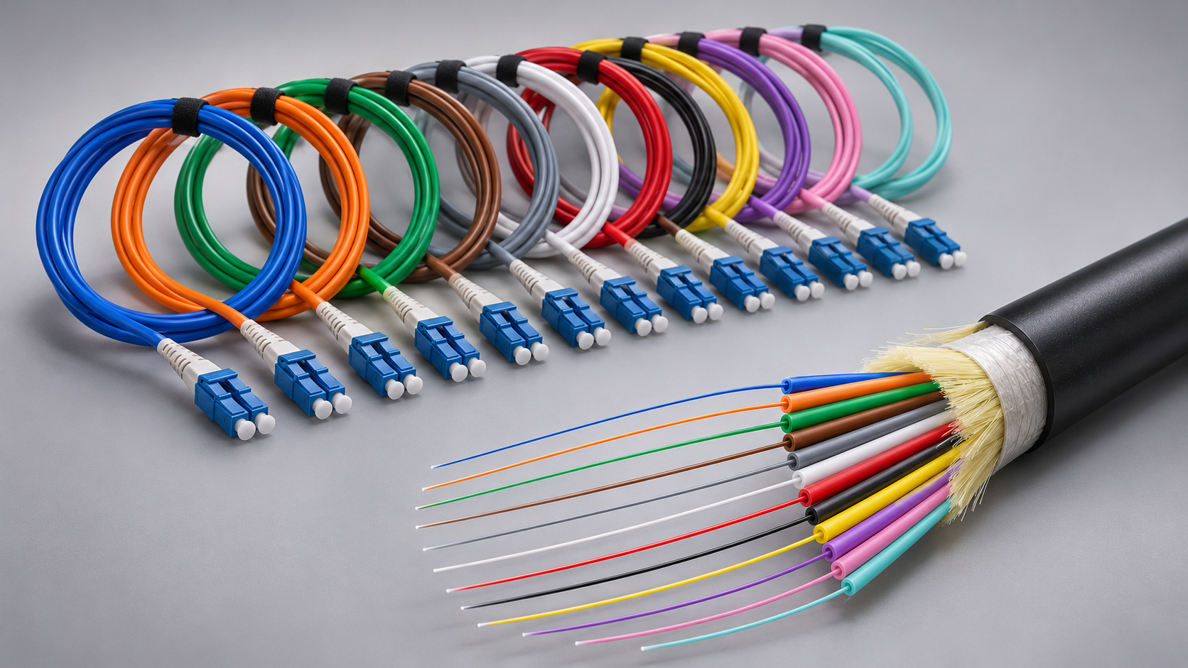
The buyer problem is straightforward. Misidentified fibers at the splice trailer mean pigtails fusion-spliced onto the wrong cores, patch panel port maps that do not match the field, and troubleshooting sessions where a fault on fiber 47 is traced to a cord that is actually fiber 74. On a route with 144 cores, a single tube miscount can shift the entire assignment plan, and rework means re-opening closures, re-splicing, and re-testing — often under pressure because the customer wants the link live. Crews in a hurry skip re-counting, and the errors propagate into the documentation that everyone downstream relies on.
This is why the color code belongs in your purchase specification, not just in your installer's method of procedure. A cable that follows the industry-standard fiber sequence consistently, with tube and unit identification printed clearly on the datasheet and the cable legend, lets your crew count once and splice immediately. A cable with an undocumented local variation forces a full re-count per reel and an updated port map per section. Procurement teams who treat the color code as an acceptance-relevant item — verified at incoming inspection, before the reels go into the trench — avoid the most expensive category of field delay: the kind that only shows up during splicing.
The same logic applies indoors. In a data center or campus riser, distribution cable and indoor tight-buffered cable terminate directly onto panels where every port is labeled by fiber number. A technician who trusts the color sequence can fan out, terminate, and label in one pass. One who cannot will verify every fiber with a light source and power meter, which on a dense panel can take longer than the termination itself.
The Standard Behind the Colors: EIA/TIA-598 and the 12-Fiber Sequence
The color sequence used across most of the fiber optic industry comes from EIA/TIA-598, with the parallel international convention IEC 60304 covering essentially the same ground. These standards define the identification colors for fibers, buffer tubes, and units so that a technician trained on one manufacturer's cable can pick up another manufacturer's reel and count it the same way. The convention is widely adopted across the industry, but it is a convention applied by manufacturers rather than a performance guarantee written into your purchase order — which is why the datasheet issued with the order remains the controlling document.
The core of the standard is a repeating 12-color sequence. Fiber 1 is blue, and the sequence runs through orange, green, brown, slate, white, red, black, yellow, violet, rose, and aqua, in that order. For cables of 12 fibers or fewer, the sequence maps directly one-to-one onto the fibers. The table below shows the sequence exactly as field crews call it out.
| Fiber Number | Color | How It Is Usually Called Out |
|---|---|---|
| 1 | Blue | Blue |
| 2 | Orange | Orange |
| 3 | Green | Green |
| 4 | Brown | Brown |
| 5 | Slate | Slate (sometimes called gray) |
| 6 | White | White |
| 7 | Red | Red |
| 8 | Black | Black |
| 9 | Yellow | Yellow |
| 10 | Violet | Violet (sometimes purple) |
| 11 | Rose | Rose (sometimes pink) |
| 12 | Aqua | Aqua (light blue-green) |
Two naming notes worth passing to your field teams. First, slate and gray refer to the same position — fiber 5 — but drawings from different contractors may use either word, so agree on terminology before the splice plan is issued. Second, rose and violet are close enough in the field that under poor lighting or through dirty gloves, crews sometimes confuse them. A clean work surface and a printed sequence card taped inside the splice trailer lid solve most of these problems.
The sequence also extends beyond the fibers themselves. In loose tube outdoor constructions, buffer tube colors follow the same 12-color order, and the fibers inside each tube repeat it. That symmetry is what makes the system scalable — and it is what the next section builds on for higher fiber counts.
Beyond Fiber 12: Units, Tracers, and Higher Fiber Counts
The 12-color sequence does not stop at 12 fibers; it repeats. What changes at higher counts is how the cable groups the repeats so that fiber 13 does not become indistinguishable from fiber 1. Above 12 fibers, cables are organized into units — buffer tubes in a loose tube design, or binder groups in a ribbon or unitized tight-buffered design — and each unit carries its own identification layer on top of the repeating fiber sequence.
The common methods, per industry convention, are colored unit binders, tracer stripes, and ribbing. A binder thread or stripe printed on each unit carries one of the 12 colors, so unit 1 is blue-bound, unit 2 orange-bound, and so on. Within each unit, the fibers repeat the standard sequence from blue to aqua. Ribbing — a raised ridge molded into a buffer tube — typically marks a specific unit position, often the first, so a crew can anchor the count. The exact method varies by manufacturer and construction, so the scheme printed on the datasheet and cable legend governs; do not assume the binder convention of your previous supplier carries over.
Walking through the common counts shows how the arithmetic works. A 24-fiber cable is typically two units of 12: fibers 1–12 in unit 1 (blue), fibers 13–24 in unit 2 (orange), with fiber 14, for example, being the second fiber (orange) inside the orange unit. A 48-fiber cable is four units, so fiber 31 sits in unit 3 (green) and is the seventh fiber (red) within it. A 72-fiber cable runs six units; fiber 60 is the last fiber (aqua) of unit 5 (slate). A 144-fiber cable — the upper end of the 2–288 core range typical for loose tube outdoor constructions — uses 12 units of 12, which means the full sequence maps twice: unit colors blue through aqua, and fiber colors blue through aqua inside each unit. The identification rules for these higher counts are the same industry convention, but the specific construction — tubes per cable, fibers per tube — is a design choice confirmed on the fiber optic cable datasheet issued with your order.
Why does this matter at the purchase stage? Because a crew that has internalized the counting logic for the cable actually delivered can strip, count, and assign 144 cores in minutes. A crew handed a cable whose unit scheme was never documented will count, re-count, and still risk a systematic error that repeats across every splice point on the route. When you evaluate suppliers for a high-count build, ask specifically how units are identified and request a copy of the print legend. Any manufacturer shipping at volume — a facility running 3,500+ product configurations, as Nexora does across its Shenzhen production lines — will have this documented per configuration; if a supplier hesitates on that question, treat it as a signal about what else may be undocumented.
One final caveat for international buyers: a few manufacturers and regions apply local variations to the unit identification layer, even when the base 12-fiber sequence is standard. If your route spans multiple cable suppliers — common on long-haul builds phased across seasons — brief your splicing lead on each cable's scheme before the first closure is opened. Five minutes with the datasheet at the reel staging area is the cheapest quality control you will ever perform.
Reading a Loose Tube Outdoor Cable: Tube Colors and Fiber Colors Together
Indoor patch cords teach you one color sequence. Outdoor loose tube cables teach you two, and you have to read them in the right order. In a loose tube outdoor cable built to the conventional scheme, the gel-filled buffer tubes themselves follow the standard 12-color sequence under EIA/TIA-598, and the individual fibers inside each tube repeat the same sequence again. That layered structure is what makes high counts manageable: instead of 144 loose fibers under one jacket, you get 12 identifiable tubes of 12 fibers each.
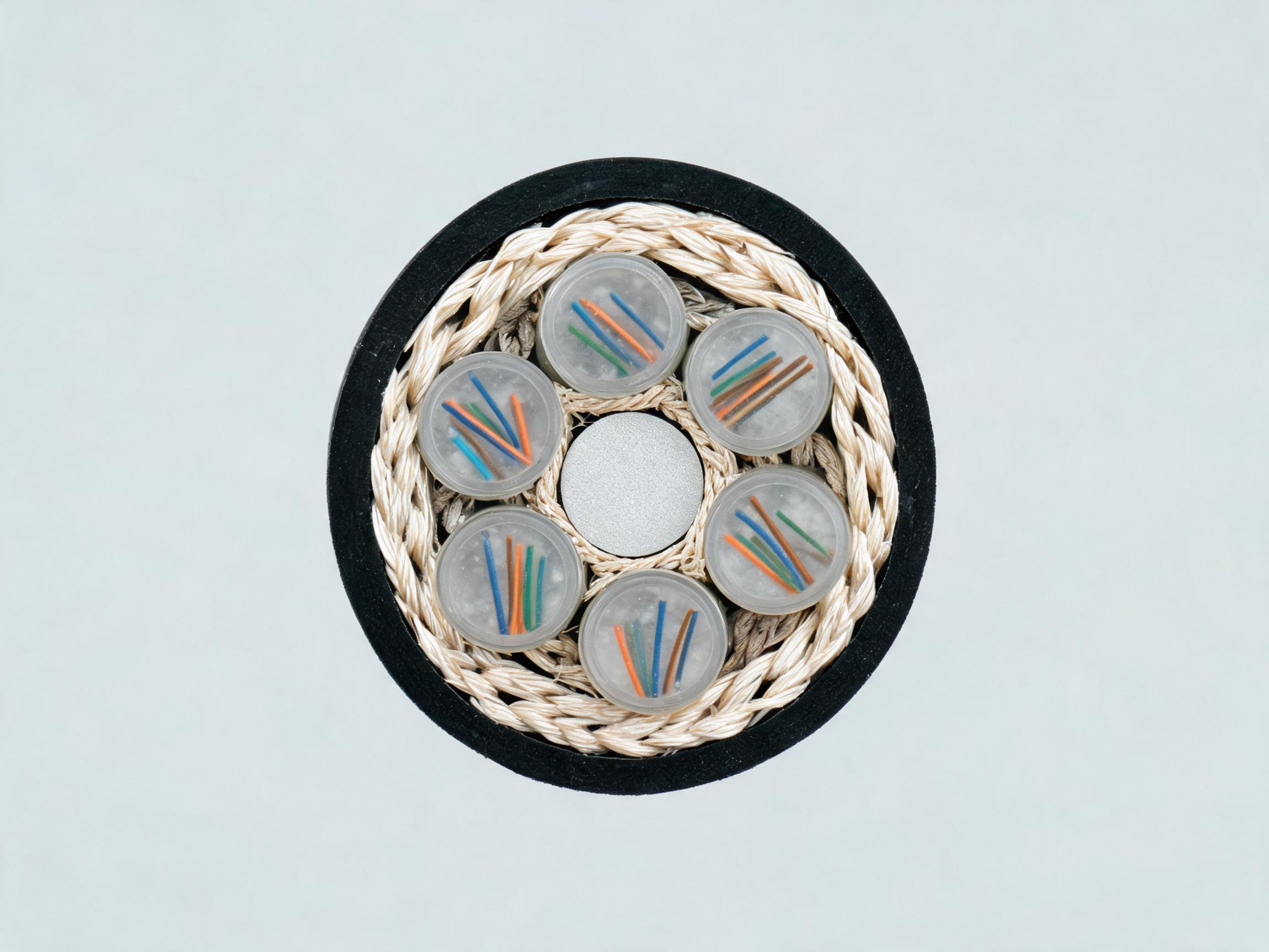
The arithmetic behind the structure is simple and worth memorizing before your next trench opens. Total fiber count equals the number of buffer tubes multiplied by the number of fibers per tube. A 24-fiber cable is commonly two tubes of 12. A 48-fiber cable is four tubes of 12. A 72-fiber cable is six tubes of 12, and a 144-fiber cable is twelve tubes of 12. Counts that do not divide evenly into full tubes exist, and when they do, some manufacturers fill the last tube partially while others adjust the fibers-per-tube figure across the cable. You cannot assume which convention applies; the datasheet and the print legend on the jacket govern, and it takes one minute to confirm before the cable leaves the drum.
Tube colors follow the same order as fibers: tube 1 blue, tube 2 orange, tube 3 green, tube 4 brown, tube 5 slate, tube 6 white, and so on through the full sequence. Inside each tube, fiber 1 is blue, fiber 2 is orange, and the sequence repeats. Some cables add a tracer fiber, often a natural or transparent fiber, in each tube as an aid; whether a tracer is present and how it counts is a manufacturer-specific detail you confirm on the datasheet before anyone starts splicing.
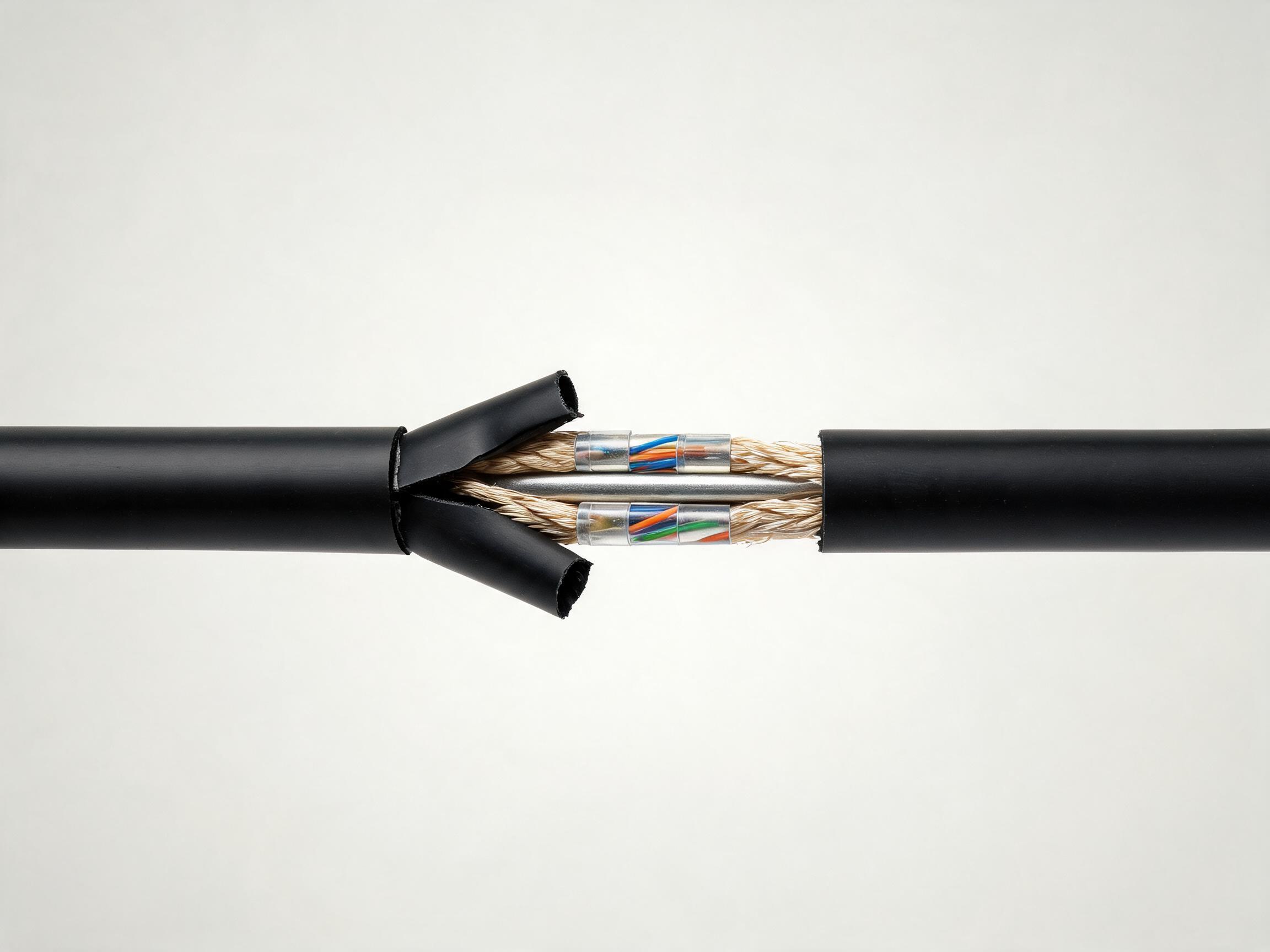
Worked Example: Finding Fiber 37 in a 144-Core Cable
Suppose your splicing crew is standing over a 144-core cable and the assignment sheet calls for fiber 37. Here is the counting logic, stated step by step so a field technician can repeat it on any count.
First, confirm the cable structure from the datasheet: a 144-core cable in the conventional arrangement is 12 buffer tubes with 12 fibers per tube. Second, work out which tube holds the fiber. Divide the fiber number by the fibers per tube: 37 divided by 12 gives 3 with a remainder of 1. That means three full tubes, fibers 1 through 36, come before it. Third, interpret the result: fiber 37 sits in tube 4, at position 1 within that tube. Fourth, identify the tube: under the standard sequence, tube 4 is brown. Fifth, identify the fiber: position 1 in any tube is the blue fiber. So fiber 37 is the blue fiber inside the brown tube, counted from tube 1 in the direction the manufacturer defines.
Two cautions belong right next to that answer. The counting direction matters: some manufacturers number tubes clockwise when viewed from one end of the drum and others count from a marked reference tube, so a crew that assumes the wrong direction will splice the wrong pair and only find out at acceptance testing. And the fibers-per-tube figure is not universal across all counts and all makers; some cables use six fibers per tube, some use ten or twelve, and partial tubes appear on non-round counts. State the convention clearly on your splice sheets, confirm the per-tube count and the tube numbering direction against the datasheet issued with the order, and write both onto the drum tag before the jacket is stripped. Thirty seconds of paperwork prevents a re-splice.
The same layered logic applies when you plan ODF terminations in advance. If your design maps tube 4, fiber 1 to a specific panel port, your splicers and your testers work from the same reference, and the as-built documentation matches the plant. That consistency is what turns a color code from trivia into a project tool.
Jacket and Connector Colors on Indoor Cables and Patch Cords
Outside the plant, color identifies position within a cable. Inside the data center and on the patch panel, color identifies the fiber type at a glance. The conventions below are widely followed across the industry, though they are conventions, not guarantees, and a few manufacturers or regions apply local variations. Treat them as your first read, not your last.
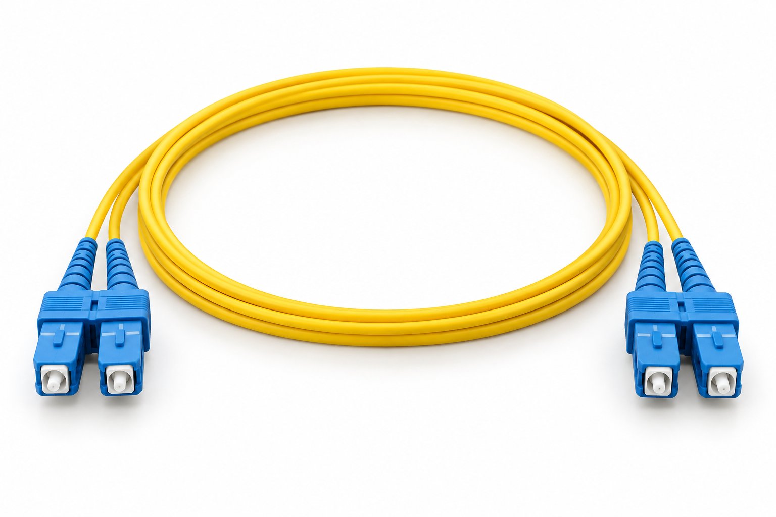
Jacket colors are the quickest signal on a shelf of patch cords. Yellow almost always means single mode. Orange means OM1 or OM2 multimode. Aqua means OM3 or OM4 multimode, with some makers labeling OM4 violet instead. Lime green means OM5, the wideband multimode fiber intended for shortwave wavelength division multiplexing. On the connector end, the housing color tells you the polish: blue for single mode UPC, green for single mode APC, and beige or black for multimode connectors regardless of the polish-style naming used on multimode grades.
The practical value shows up the moment someone hands you a cord in a hurry. A yellow jacket with blue connectors is a single mode UPC assembly, the standard choice for a SC-SC single mode G.652D patch cord on an ODF. An aqua jacket with black or beige multimode connectors points to an OM4 assembly such as an LC-LC duplex multimode OM4 patch cord. A yellow jacket with green connectors is single mode APC, which matters enormously if the panel ports are UPC. The jacket and the housing should agree; when they do not, someone has mixed stock, and that cord does not go into a live link until it is measured.
| Jacket Color | Convention | Typical Use |
|---|---|---|
| Yellow | Single mode (G.652D and similar) | Carrier and FTTx ODF patching, single mode links, patch cords and pigtails |
| Orange | OM1 / OM2 multimode | Legacy indoor backbone runs, older premises installations |
| Aqua (sometimes violet for OM4) | OM3 / OM4 multimode | Data center horizontal and backbone cabling, 10G-100G short-reach links |
| Lime green | OM5 multimode | Shortwave WDM multimode links in modern data centers |
Connector housing colors carry equal weight. A blue housing on an SC or LC connector signals a single mode UPC end face; a green housing signals APC with its angled, 8-degree polish. Beige or black housings indicate multimode. If you keep both UPC and APC stock on the same shelf, as most integrators do, the housing color is the control that keeps the two apart. If you are unsure which polish your network should use at all, the choice between UPC and APC connectors deserves its own decision before you order, because mixing them in one link is one of the most expensive small mistakes in the trade.
Jacket Color Is Not a Fiber Grade: Read the Print Legend
Here is the trap experienced buyers already know: jacket color is paint, not specification. The color conventions exist because they are useful, but nothing physically prevents a yellow jacket from carrying multimode fiber or an aqua jacket from carrying OM3 when the label says OM4. Counterfeit and mislabeled assemblies circulate precisely because buyers accept color as proof. The only reliable identification is the print legend running along the jacket and the datasheet behind it.
Every reputable cable carries a repeating legend with the manufacturer, the fiber type and standard, the count, the manufacturing date and often the reel number. Read it before the cable is pulled, and photograph it on the drum; once the cable is in a duct, the legend you did not record is the legend you will wish you had. Cross-check the legend against the datasheet before the order ships, a step covered in detail in our guide to reading a fiber optic cable datasheet before you buy. A datasheet that states the fiber category, the attenuation figures and the color scheme is worth more than any jacket color, and any performance figure on it, such as typical attenuation of 0.36 dB/km at 1310 nm for G.652D, is a typical value to confirm against the specification sheet issued with the order.
The same discipline applies indoors. An indoor tight-buffered fiber optic cable and a distribution cable may share jacket colors with completely different constructions, fire ratings and fiber counts, and the legend is what separates them on a crowded riser. When your crew terminates an ODF with pigtails, the same rule holds in reverse: the pigtail jacket tells you the fiber type at a glance, but the connector housing color and the datasheet tell you the polish, and only a measurement on delivery tells you the assembly actually meets its insertion loss figure. Color gets you close; the legend and the test report close the case.
Using the Color Code at the ODF and Patch Panel
The color code earns its keep at the termination point. A cable drum with 144 correctly colored fibers is still a liability if the splicing crew at the ODF loses track of which fiber lands on which port, because a single swapped connection can take a production link down without any visible fault on the panel. The discipline starts before the first strip: the crew leader should have the cable's fiber allocation sheet, the panel port map, and a marker set, and the fiber number from the drum should be written onto the labeling scheme agreed with the network owner.
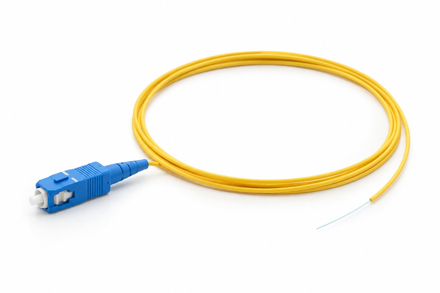
The standard termination method in most ODFs and rack-mounted patch panels is a factory-terminated fiber optic pigtail spliced onto each cable fiber. The pigtail gives you a consistent 0.9 mm tight-buffered tail and a connector polished under factory control, and the splice is the only field variable left. Because pigtails are supplied in the same 12-color sequence, the pigtail tray itself becomes a second reference: fiber 1 of the cable splices to the blue pigtail, fiber 2 to orange, and so on. If the crew keeps the cable fiber count and the pigtail position in step, misidentification becomes nearly impossible without two simultaneous errors.
Behind the pigtails, adapters hold the front panel in place. Housing color on the adapter and connector is your first sanity check: blue housings for single mode UPC, green for single mode APC, beige or black for multimode, following industry convention. A row of LC/APC duplex adapters feeding an FTTx or carrier link should never sit next to blue UPC ports in the same panel without physical separation, because the two are mechanically compatible and easy to cross-plug. Where the panel is single mode UPC, SC/UPC adapters with blue housings keep the polish type visible at a glance even from a few meters away.
Labeling practice is where experienced crews separate themselves from average ones. Every port should carry three pieces of information: the panel identifier, the port number, and the source fiber reference in the form of cable ID, tube number, and fiber number. A label reading CAB-07/T08/F05 means fiber 5 of tube 8, and it can be traced back to the drum end in seconds using the color sequence alone. Write the label before splicing, not after, and photograph the completed panel. On multi-cabinet ODFs, keep the fiber sequence direction consistent across all cabinets so a technician moving from one rack to the next does not have to relearn the counting direction.
The planning stage matters as much as the work itself. Port groupings, adapter types, splice tray layout, and slack management should all be fixed before the cable arrives, and our guide on how to plan an ODF and rack termination for a fiber network walks through that process in detail. A well-planned ODF uses the color code as the backbone of the documentation: the port map references colors and numbers, so future moves, adds, and changes can be executed by any technician who knows the standard 12-fiber sequence, not only by the crew that built the panel.
One practical note on duplex ports: duplex patch cords pair two fibers, and the transmit/receive orientation (A to B, or position 1 to position 2) must be consistent end to end. Color coding identifies the fibers; it does not define the polarity scheme. Confirm the polarity convention with the network owner before the panel is populated, because flipping a duplex pair is one of the most common causes of a link that will not come up despite a clean OTDR trace.
The Mistakes That Cost the Most on a Color-Coded Route
Polish mismatch. The single most expensive error at termination level is cross-mating UPC and APC connectors. Both are physically compatible, so nothing stops a technician from plugging a green APC patch cord into a blue UPC adapter. The consequence is immediate: air gap between the two polish geometries, insertion loss typically several dB, and return loss far below specification. APC return loss depends on the angled physical contact, typically 60 dB or better on factory-terminated cords, while UPC cords typically achieve 50 dB or better; mating the two destroys both figures. The colors are there to prevent exactly this: blue housing means single mode UPC, green means single mode APC. Train crews to treat green and blue as non-interchangeable, and if the reasons behind the polish types are unclear, our article on the difference between UPC and APC connectors explains when each should be specified.
Miscounting on high fiber counts. The 12-color sequence is easy to hold in your head. Counting through 96 or 144 fibers by eye is not. The arithmetic is simple but unforgiving: in a 12-tube cable, fiber 37 sits in tube 4 (because 36 fibers, three full tubes, precede it) at position 1, so you are looking for the fourth tube in the color sequence and the blue fiber inside it. Errors happen when crews lose track of whether they have counted fibers or tubes, or when they skip a gel-filled tube that is hard to open. The fix is procedural: count tubes first, then fibers within the tube, and have a second person verify before any splice is made. On a 144-core route, a single miscount discovered after splicing costs a re-splice, a re-test, and often a re-label.
Tracer and unit-binder confusion between manufacturers. Above 12 fibers, the standard does not force a single implementation. Cables group fibers into units identified by colored unit binders, tracer stripes, or ribbing, and the exact method varies by manufacturer. A crew that has worked for years on one brand's 96-core cable, where tubes carry a colored binder over the base color, can misidentify fibers on another brand's cable that uses striped tracers instead. This is a real risk on multi-vendor routes where different sections of the same link come from different suppliers. The datasheet and print legend govern: confirm the unit identification scheme for every drum before the crew starts, and never assume that a tracer convention from one cable applies to the next. Our article on reading a fiber optic cable datasheet before you buy covers what to check.
Skipping the post-splice check. A splice that looks clean under the fusion splicer's camera can still be a poor splice, and a correctly colored fiber is not necessarily a correctly connected one. After splicing, every fiber should be checked with a light source and power meter or an OTDR, and a quick pass with a visual fault locator (VFL) catches gross faults, broken splices, and mis-plugged cords instantly. A VFL also confirms continuity end to end, which is the one thing the color code cannot prove on its own. For crews choosing between field terminations, our comparison of fusion splicing versus mechanical splicing outlines the trade-offs; whichever method you use, verification after termination is not optional.
How to Specify Color Coding in Your RFQ
Color coding errors are cheapest to prevent on paper. When you issue a fiber optic cable RFQ, state explicitly that the fiber and buffer tube sequence shall follow EIA/TIA-598 (or IEC 60304 if your market requires it), rather than leaving the supplier to assume a house standard. Most cable manufacturers default to the standard sequence, but writing it into the RFQ removes ambiguity, especially when the order will be split across production batches or when a second supplier will feed part of the route.
If your count exceeds 12 fibers, ask the supplier to confirm the unit identification scheme in writing: how units or tubes above the first twelve are marked, whether binders, tracer stripes, or ribbing are used, and how the scheme is documented on the datasheet. Ask for a sample of the print legend as well. The legend should show meter marking, cable type, fiber count, manufacturer identification, and the year, and a consistent legend makes field verification and acceptance testing far easier.
For patch cords and pigtails, specify the connector housing colors along with the polish type, so a blue UPC cord can never be shipped where a green APC was intended. If you are ordering duplex patch cords, state the polarity scheme and the cord diameter. A LC/LC duplex single mode patch cord, for example, should be specified by length, jacket material (LSZH or PVC), polish type, and duplex clip orientation, not just by the connector names. Custom requirements, such as a non-standard color sequence or printed fiber numbering, are possible but should be raised at RFQ stage rather than after the order is placed, since they affect production planning and lead time. The clearer your color coding requirements are at quotation, the fewer surprises you will meet when the drums and cartons arrive on site.
How the Factory Verifies Color Sequence and Fiber Identity Before Shipment
A color code is only useful if it is correct when the drum arrives on site. That is why color sequence and fiber identity are checked at Nexora before anything leaves the factory, not left to the installer to discover. Quality control runs across more than 30 QC stations covering incoming material, component, in-process, functional, visual, final and packaging inspection, and the color-related checks sit inside that chain rather than being an afterthought at the end.
For outdoor loose tube cables, continuity is confirmed on every finished reel before dispatch. Fibers are traced end to end against the expected color sequence, and attenuation is measured on the same fibers so that any optical anomaly is linked to a specific, identifiable position on the drum. For a cable such as the outdoor G.652D loose tube cable, typical attenuation figures such as 0.36 dB/km at 1310 nm and 0.22 dB/km at 1550 nm are typical values, and the measured results for your reel can be supplied with the shipment on request. If your acceptance team needs the test data as a condition of delivery, state it in the RFQ so it is planned into the process rather than arranged at the last minute.
Terminated assemblies get a different check, because on a patch cord or pigtail the color code question overlaps with the connector question. Every cord is measured before packing, and end-face inspection is carried out on terminated assemblies to confirm polish quality before shipment. A fiber optic pigtail with typical insertion loss of 0.3 dB or better and return loss of 50 dB or higher on UPC end faces is only useful to the installer if the connector color also matches the fiber type it carries, so both are verified. Insertion loss and return loss figures are typical production values and release limits, and exact limits should be confirmed against the specification sheet issued with the order.
The third element is the jacket itself. The print legend on the jacket carries the cable identity, fiber count and, where applicable, the marking that helps you confirm what is inside the drum. On a 144-core route, that printed line is the fastest cross-check against the datasheet before the drum is even lifted off the truck. Packaging inspection at the final station includes confirming the reel length and labeling match the order, because a drum marked as 4 km that is actually shorter will break your color-coded segment plan at the splice point.
None of this replaces your own verification on receipt, and it is not meant to. What it does is reduce the probability that the verification finds a problem. Buyers who treat factory testing and site verification as two halves of the same acceptance routine consistently close out fiber projects with fewer disputes and fewer re-splices.
Buyer FAQ
Do all manufacturers use the same color code?
Most follow EIA/TIA-598 or IEC 60304, so the first 12 colors are predictable across the industry. Above 12 fibers, however, the method for distinguishing units varies between manufacturers, and a few regions or factories apply local variations. The print legend and datasheet issued with your order govern, so confirm the scheme before installation starts rather than assuming it matches a previous supplier.
Can I order a custom color sequence or jacket printing?
Custom requirements are part of the normal production range at Nexora, which covers more than 3,500 product configurations with roughly 300 new configurations added each year. Custom jacket printing, modified unit identification schemes and non-standard counts are all handled, typically with higher minimum order quantities than standard items. Discuss the scheme during quotation so the datasheet can document it clearly.
How do I verify the color code when the cable arrives?
Check the print legend against the datasheet, confirm the drum length on the label, then strip a short section at the drum end and trace the first few tubes and fibers against the expected sequence. A visual fault locator is a practical tool for confirming continuity on individual fibers before the drum is installed, and it also serves you later during troubleshooting; see our guide on troubleshooting a fiber optic link with a VFL.
Does the color code also apply to pigtails and patch cords?
Yes, in two ways. The fiber inside follows the same identification logic, and the connector housing color follows the industry convention: blue for single mode UPC, green for single mode APC, beige or black for multimode. Since every cord at Nexora is measured before packing, the connector color on a shipped assembly should always match the fiber type stated on the label, but it costs nothing to confirm on receipt.
What should I do if two fibers look the same color?
In higher-count cables, unit binders or tracer stripes distinguish repeated sequences, and under site lighting some colors such as slate and black, or rose and orange, can be hard to separate. Use the unit number plus the fiber position within the unit rather than color alone, check against the datasheet scheme, and record both in your documentation. If ambiguity remains, do not splice on assumption; re-verify with a VFL or an OTDR trace.
How does color coding help acceptance testing?
Acceptance testing produces per-fiber results, and those results are only meaningful if each test trace maps unambiguously to a physical fiber. A consistent color scheme lets your test sheet reference tube number, fiber color and fiber number together, which makes any failed result traceable to an exact position for repair. It also shortens the acceptance meeting, because both parties are reading the same fiber identities from the same documented scheme.
Getting the Color Code Right Before Your Next Order
The color code is a small detail that decides whether a 144-core route terminates in a day or a week. A few takeaways from buyers who get it right:
- Confirm the scheme in writing before production. For counts above 12 fibers, ask how units are distinguished and get it on the datasheet, not in an email thread. Our article on reading a fiber optic cable datasheet before you buy covers what to look for.
- Match connector housing color to fiber type across the whole order. Blue for single mode UPC, green for single mode APC, beige or black for multimode. Mixing polish types on one link is an expensive error; if you are undecided, see our comparison of UPC and APC connectors.
- Document tube-and-fiber mapping before splicing begins. Write down unit number, fiber color and fiber number for every termination, and keep that sheet with the ODF records.
- Verify on receipt, not at the splice point. Print legend, drum label, and a short stripped-back check at the drum end take minutes and prevent days of rework.
- Put test reports and labeling requirements in the RFQ. If you need per-reel test data or specific print legend content, it belongs in the enquiry so it is priced and planned. Our guide on what to include in a fiber optic cable RFQ gives a practical checklist.
Color coding rewards buyers who treat it as a specification item rather than a factory default. When the scheme is documented, printed and verified at both ends, the same 12-color sequence that looks trivial on a datasheet becomes the backbone of a clean, testable installation.
If you are planning a route and want the color scheme, drum lengths and fiber counts locked down before production, share your core count, route type and required drum lengths with our team. Whether the job is direct burial, duct or aerial, and whether you need loose tube cable, pigtails or patch cords alongside it, we will confirm the identification scheme in the datasheet and support it with per-reel test data on request. You can request a quotation with those details and we will come back with a documented proposal.