
A buyer's guide to planning fiber optic cable and patch cords for a 5G FTTA base station: fronthaul chain, fiber count, cable construction by section, loss budget, patch cord specs, polarity, UPC vs APC, installation and testing.
What FTTA Changes About Your Fiber Plan
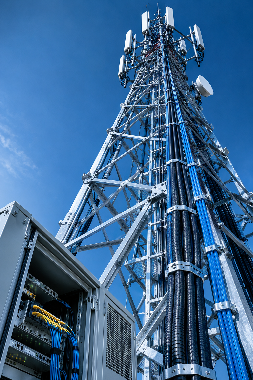
Fiber-to-the-antenna (FTTA) is the deployment model in which the fiber link runs all the way from the baseband unit (BBU) at the base of a cell site up to the remote radio units (RRUs) mounted beside the antennas at the tower top. In earlier radio architectures, the radio equipment sat in the equipment shelter and short coaxial runs carried the RF signal to the antenna. 5G changed that: wider channel bandwidths, massive MIMO antenna arrays and higher-order modulation generate enormous amounts of fronthaul traffic between baseband processing and the radio, and the CPRI/eCPRI-class data rates involved make it far more practical to digitize the signal and move the radio hardware to the tower top, connected by fiber instead of RF feeders.
That architectural shift has a direct consequence for fiber planning. The distances involved are short - typically tens of metres on a rooftop or lattice tower to a few kilometres across a site or cluster - so attenuation over the span itself is rarely the limiting factor. What changes is the environment and the termination density. A fronthaul link passes through vertical risers, outdoor cable trays, duct sections and open tower structure, all fully exposed to weather, UV, wind vibration and temperature cycling. It also contains more mated connector pairs and field splices per metre than a long-haul or buried backbone run, because the link is repeatedly broken out and re-terminated as it moves from the shelter to the tower-top equipment.
The practical result is that FTTA fiber decisions differ from a standard buried backbone in three areas. First, cable construction: an outdoor-rated loose tube design, and in exposed sections an armored design, replaces the indoor and intra-facility products a data center would use. Second, fiber count: the count is driven by the number of radios and sectors at the top, plus sparing, rather than by a long-haul topology. Third, termination: short factory-terminated patch cords and pigtails at the equipment ends, where a repair after commissioning is slow and expensive, matter more than they would on a ground-level route with easy access. The sections below work through each of these in turn.
The Fronthaul Chain: From BBU to the Tower-Top Radio
It helps to map the physical chain before choosing products. At the bottom of the site, the BBU sits in the equipment shelter or outdoor cabinet, together with the power and transmission equipment. The fronthaul fiber starts here, normally leaving the shelter through a penetration or cable tray and running across the compound toward the tower base.
Somewhere along this path there is usually a splice or cross-connect point. On many sites this is a closure or cabinet near the tower base where the feeder cable from the shelter is spliced to the riser cable that climbs the structure, or where a multi-fiber cable is broken down into the individual fiber groups feeding each radio. The exact location varies with the site design - some operators put the cross-connect inside the shelter, others at the tower base in a dedicated cabinet - but the function is the same: it separates the easily replaced riser and patch sections from the more permanent buried or ducted portion, and it provides the fiber-management space for splices and breakout.
From the cross-connect point, fiber climbs the tower. This is the most exposed part of the chain: a vertical run attached to steelwork, subject to UV, wind-induced vibration of the tower itself, wide day-night temperature swings and, on some structures, rodent and bird interference. At the top, each RRU or integrated antenna unit is mated to the fronthaul fibers through short factory-terminated patch cords, typically with LC connectors, so that a failed radio or cord can be swapped without re-splicing at height. Each sector may carry two or more fronthaul fibers, depending on the radio configuration and the operator's architecture.
The termination points are the practical key. The link is only permanently spliced at the cross-connect; everything above it, and the final metres into the BBU and each RRU, should be mated connections using factory-terminated cords. That way, the difficult-to-access sections can be maintained by replacing a cord, and the loss-critical connector pairs are factory-polished rather than field-terminated. When planning the run between the shelter and the tower base, a distribution-type outdoor cable with a moderate core count is often the right intermediate product for this breakout stage; see the distribution fiber optic cable for that role.
Why a Tower Site Is a Harsh-Environment Job
FTTA fronthaul is a short-reach link by distance standards, but the environment it runs through is closer to an industrial installation than to a data center. Several stress factors act simultaneously, and each points to a specific cable attribute.
Ultraviolet exposure is constant. A cable climbing an open lattice tower has no shade and no conduit above the riser; a PVC or non-rated outdoor jacket will chalk, embrittle and crack over time. A black PE jacket with proper UV stabilization is the baseline requirement for anything above the shelter wall. Wide temperature swings compound this - a cable on a tower experiences the full ambient range, from sub-zero nights to surface temperatures well above air temperature in direct sun. The -40°C to +70°C operating range listed on outdoor loose tube constructions exists precisely for this kind of duty; confirm the rated range against the datasheet for your specific climate zone.
Wind-induced vibration matters more than many buyers expect. The tower moves, the cables attached to it move with it, and clamped points become flex points over years of service. A loose tube, gel-filled construction tolerates this far better than a tight-buffered indoor design, because the fiber floats inside the tube rather than being coupled directly to the jacket. Condensation is the third moisture path: temperature cycling across the dew point drives water into any imperfectly sealed closure or cable end, which is why gel-filled tubes and water-blocking jackets are standard for the outdoor portions.
On some structures, physical interference is a real risk - rodents climbing the tower, birds pecking at jacketed cables, or incidental abrasion against steelwork. Where the route is exposed or rodent-prone, an armored construction is the appropriate response rather than simply thickening the jacket. Finally, and arguably most importantly: after the site is commissioned and live, access to the tower top requires a tower crew and, in many regions, a work permit. Any design decision that reduces the likelihood of a tower-top repair visit - better construction, factory termination, extra spare fibers - pays for itself many times over. For a broader treatment of these selection factors, see our guide on choosing fiber optic cable for harsh environments.
How Many Fibers One Site Actually Needs
Fiber count for FTTA is driven from the top of the tower downward. Start with the radios: each RRU or integrated antenna consumes one or more fronthaul fibers depending on the radio generation and the operator's fronthaul architecture. A three-sector site with two RRUs per sector, for example, may consume six to twelve fibers at the tower top before any sparing is added. The number per sector is a function of the equipment specification, not of the cable catalog, so it must come from the radio vendor's documentation for the specific deployment.
Then add sparing and growth. Because tower access is expensive after commissioning, deliberate over-provisioning of the riser is the common planning response: spare fibers that are spliced and connectorized at the cross-connect but left dark at the top are the cheapest insurance available against a future radio addition or a fiber failure. A common planning approach is to add at least one full radio's worth of spare fibers per site, and more on structures where a later capacity upgrade is foreseeable. Maintenance spares also matter - if a fiber is damaged at height, having spare fibers in the same cable lets the crew re-patch instead of re-pulling the riser.
Translating this into a cable core count is then straightforward arithmetic with a rounding decision. If the consumed count plus sparing lands at, say, 18 to 24 fibers, a 24-core feeder cable is the natural choice; if it lands higher, 48-core or above becomes appropriate. Because outdoor loose tube cables are manufactured in discrete core counts (2, 4, 6, 8, 12, 24, 48, 72, 96, 144 and beyond, up to 288), the count you order should be the next standard size above your computed need, not an exact match. It is worth noting that core count affects more than price: outer diameter, drum weight and tensile rating all rise with core count, which matters when you are pulling cable up a structure or through tight duct. For a fuller treatment of this decision, including how to handle multi-span designs and future-proofing, see our article on choosing the right fiber count.
Which Cable Construction Survives the Climb
FTTA sites rarely need one cable type for the whole path. The run from the shelter to the tower base, the vertical riser and any pole-line span each have different mechanical exposures, and matching the construction to each section is more economical and more reliable than over-specifying one product everywhere. Three constructions cover the large majority of FTTA routes.
Standard outdoor loose tube cable for ducted and protected sections
For the buried or ducted portion between the equipment shelter and the tower base, and for risers that run inside conduit or a fully protected cable tray, a standard outdoor G.652D loose tube cable with a black PE jacket is the appropriate baseline. Its gel-filled loose tubes handle moisture and temperature cycling, and its mechanical ratings are sized for civil-works installation: for example, 2-12 core builds carry typical short-term/long-term tensile ratings of 1,500/600 N, rising to 2,700/1,000 N for 216-288 core builds; bend radius is typically 20x outer diameter during installation and 10x in service, with crush resistance in the 1,000-3,000 N/100 mm range. All of these values are catalog/typical figures - confirm against the datasheet for the specific core count you order. You can review the construction and full specification range on the outdoor G.652D single mode fiber optic cable product page.
Armored cable for exposed or rodent-prone sections
Where the route cannot be protected - an exposed compound run, a riser on a structure with known rodent or bird activity, or a section susceptible to accidental impact from site equipment - an armored construction is the right call. Steel tape or steel wire armor under a PE water-blocking jacket turns a chewed-jacket failure mode into a non-event, and it raises the mechanical envelope substantially: typical short-term tensile ratings reach 3,000 N for steel tape builds and 6,000 N for steel wire builds, with crush resistance of up to 3,000 N/100 mm (steel tape) and 4,000 N/100 mm (steel wire). Note that armor changes the handling rules too - the typical installed bend radius is 15x OD, rising to 20x OD under pull load, so the route design must accommodate the stiffer cable. A fuller decision framework for when armor is and is not justified is in our armored fiber optic cable buyer's guide, and the construction details are on the armored fiber optic cable product page.
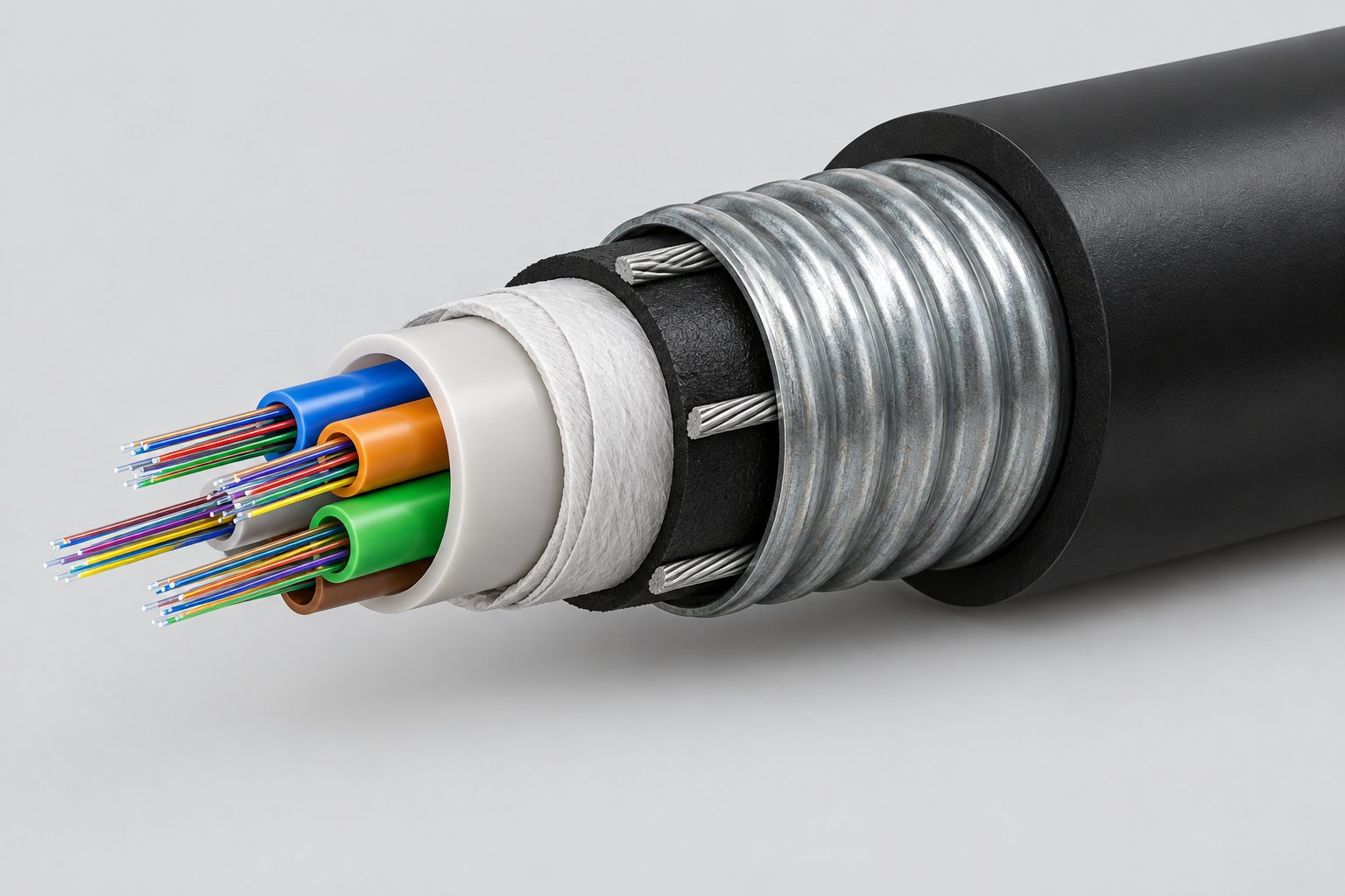
Figure-8 self-supporting cable for pole-line spans
Some sites - particularly rooftop and rural sites - include a final span on a pole line rather than in duct. For that section, a figure-8 self-supporting construction, which integrates a messenger wire alongside the fiber core, avoids the need to lash a separate support strand and handles the tension of the span directly. It is worth being precise about the decision here: figure-8 is the natural choice when a physical messenger is desired and the span is short to moderate; ADSS (all-dielectric self-supporting) is the alternative when electrical isolation from a nearby power structure matters and the cable itself must carry the full tension. We cover both options in dedicated guides on figure-8 self-supporting cable deployment and on whether ADSS is the right choice for an aerial network, and the product construction is on the figure-8 self-supporting cable page.
For the intermediate run between the equipment shelter and the tower base - the section where the fiber count is highest but the mechanical exposure is moderate - a multi-tube outdoor construction is often the best fit. Multiple gel-filled tubes inside one jacket keep the fiber groups organized for breakout at the cross-connect, and the construction scales cleanly from 24 up to 144 cores and beyond without the fiber becoming difficult to manage at the splice point. The structure is visible in the illustration below.
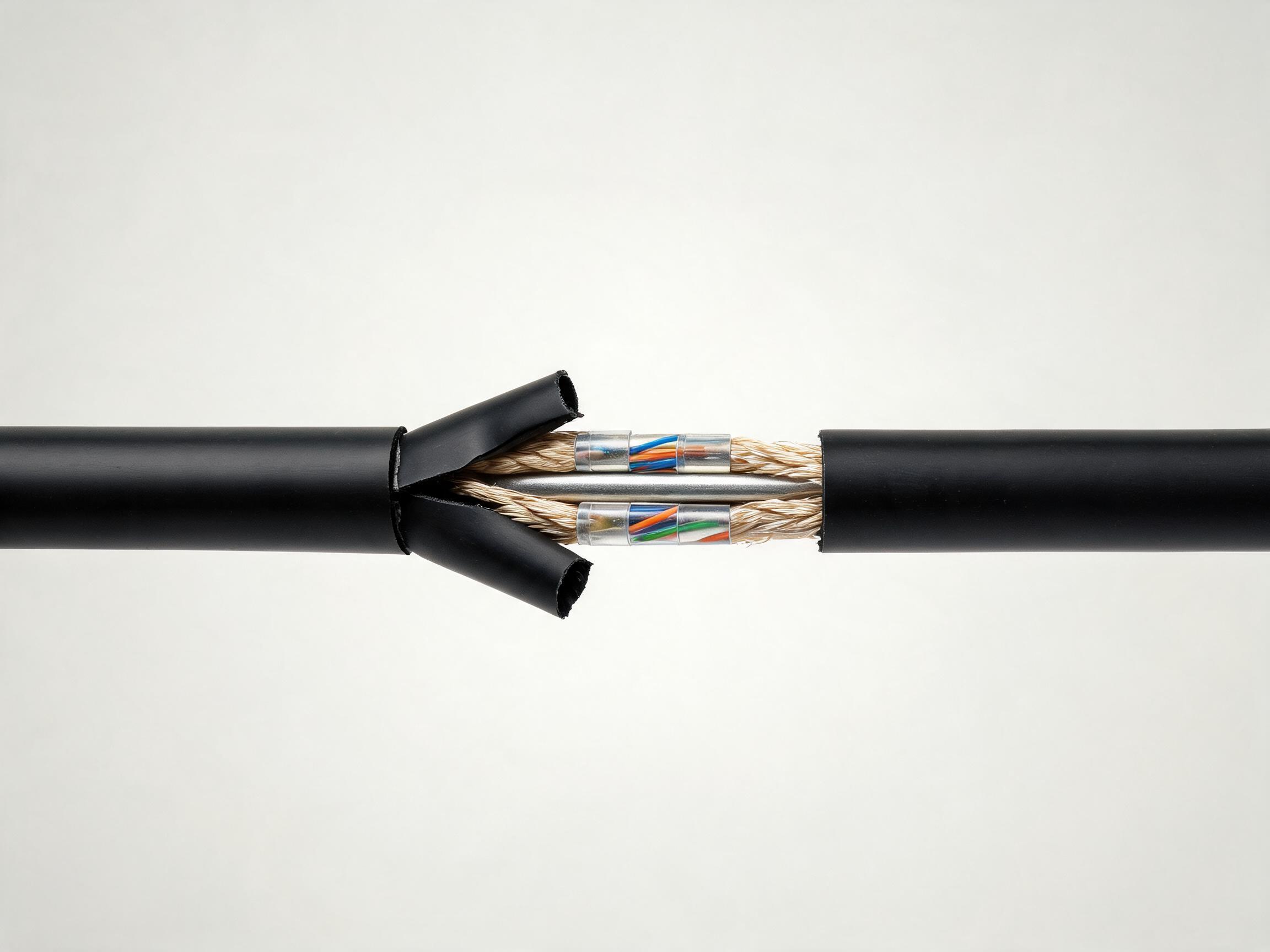
The comparison can be summarized by section: ducted or protected runs take standard loose tube; exposed or rodent-prone runs take armored; pole-line spans take figure-8; and the high-count breakout section between shelter and tower base typically takes a multi-tube outdoor construction. No single construction is mandatory for any given section - these are decision conditions, and the right combination depends on the specific route survey.
Fiber Type: G.652D as the Fronthaul Default
For the fiber inside all of these constructions, standard single mode G.652D is the default for fronthaul, and the reasoning is simple: the spans are short. G.652D's typical attenuation of ≤0.36 dB/km at 1310 nm and ≤0.22 dB/km at 1550 nm translates to fractions of a decibel over a fronthaul distance of tens of metres to a few kilometres - loss that is negligible in a budget dominated by connectors and splices. Its mode field diameter of 9.2 ± 0.4 μm is the standard geometry that all single mode connectors, splices and test equipment are built around, which keeps splicing yield high and component sourcing universal. As with all catalog values, confirm against the datasheet for the production lot. Fronthaul traffic is digital CPRI/eCPRI-class data over single mode optics designed for exactly this fiber class, so there is no performance reason to move beyond G.652D for these distances, and certainly no reason to consider multimode - the single mode vs multimode comparison explains why single mode is the correct category here.
Where a different fiber class earns its place is at the fiber-management points. Inside closures, patch panels and equipment termination boxes, fibers are routed around small spools and through tight channels, and a standard G.652D fiber exhibits increasing bend loss as the routing radius shrinks below its recommended minimum. Bend-insensitive G.657-class fiber tolerates those tight bends with essentially no added loss, which reduces a real failure mode at the panel - a fiber pressed against a closure wall or routed too tightly during a hurried maintenance visit. For the cable runs themselves, though, bend-insensitivity is not required at the radii outdoor cable constructions are designed for.
The practical rule: order G.652D for the outdoor and riser cables, and consider G.657-class fiber where tight panel routing is the dominant stress. This is not a hard requirement either way - many operators run G.652D end to end with careful fiber management and no issue. The full trade-off, including splice compatibility between the two fiber classes, is covered in our G.657 vs G.652D comparison.
A Worked Loss Budget for a Fronthaul Span
Because fronthaul spans are short but connector-dense, the loss budget is worth writing out explicitly before ordering. The example below uses a representative 2.5 km fronthaul span - BBU to tower-top radio via a cross-connect - at 1310 nm. Every value used is either a listed catalog value or a clearly labelled planning reference, not a guarantee; splice and connector figures in particular are planning references, and actual site results depend on workmanship.
The assumptions: the span uses outdoor G.652D loose tube cable with the listed attenuation of ≤0.36 dB/km at 1310 nm; the path contains 6 fusion splices (typically 0.10 dB each as a planning reference - two at the shelter end breakout, two at the tower-base cross-connect, and two at the tower-top breakout); and the path contains 4 mated connector pairs, using the LC-LC duplex single mode patch cord release limit of ≤0.3 dB per cord as the worst case per mated pair. Note that production cords typically measure better than the release limit - ≤0.2 dB is typical across production, but that is a statistical result, not a per-piece guarantee, so the budget should be built on the release limit.
| Budget item | Basis | Worst-case loss |
|---|---|---|
| Fiber attenuation, 2.5 km @ 1310 nm | 0.36 dB/km listed attenuation × 2.5 km | 0.90 dB |
| Fusion splices (6) | Planning reference of 0.10 dB per splice | 0.60 dB |
| Mated connector pairs (4) | ≤0.3 dB max per cord release limit | 1.20 dB |
| Total worst case, before margin | Sum of the above | ~2.70 dB |
Two observations follow from the table. First, the connectors and splices dominate: the 2.5 km of fiber contributes 0.90 dB, while termination contributes 1.80 dB - two thirds of the budget - even though the span is kilometres long. This is the defining characteristic of FTTA loss budgets and the reason factory-terminated cords with tight release limits are worth specifying. Second, the margin you hold back from this ~2.70 dB total should cover aging of connectors, repairs that add splices over the site's life, and measurement uncertainty. What margin is adequate depends on the optical transceiver specification and the operator's standards, so treat the number above as the fixed part of the calculation, not the complete answer.
The full method, including how to handle bidirectional testing and how to set margin, is in our fiber optic link loss budget calculation guide. Before you order any cable or cord against a budget like this, it is also worth reading the datasheet critically rather than taking the headline numbers at face value - our guide on how to read a fiber optic cable datasheet before you buy covers which figures are release limits, which are typical values, and which need written confirmation.
Patch Cords at the Tower: What to Actually Specify
On a FTTA site, factory-terminated patch cords belong at three distinct points: the BBU panel at the base of the site, the radio ports at the tower top, and the ODF or cross-connect where the outdoor span is broken out onto structured patching. Everywhere a fronthaul link mates to equipment or a patch panel, a short factory-built cord is the cleanest way to introduce a connector pair without field-terminating in difficult conditions. Field termination at height, in wind, with a power supply borrowed from the site, is a common source of connector quality problems; ordering cords cut to length avoids it entirely.
For 5G fronthaul, the specification that matches the usual equipment convention is LC duplex UPC connectors on single mode G.652D fiber. Set a per-cord insertion loss limit of 0.3 dB maximum as the release limit — this is the value every cord must meet before it ships — with production typically running at 0.2 dB or better across the population. Note that the 0.2 dB figure is a statistical property of production, not a per-piece guarantee; the 0.3 dB release limit is the contractual value, and you should confirm both against the datasheet for the exact cord you order. Return loss for UPC polish is 50 dB minimum. Jacket choice is LSZH or PVC, with cable outside diameter of 2.0 mm or 3.0 mm, and lengths can be made to order from 0.5 m to 30 m.
Length planning deserves care. Measure the real run — BBU to ODF, ODF to tower base, tower base to radio port — and add a service loop at each end for slack, connector re-work and future maintenance. A cord cut exactly to the measured distance is a trap: there is no way to re-mate or re-route it without replacing it, and tower-top access after commissioning is expensive. Ordering a standard set of site-specific lengths (for example one short length for radio ports and one longer length for the base run) is usually better than a mix of ad-hoc values, because it makes spares interchangeable across the site.
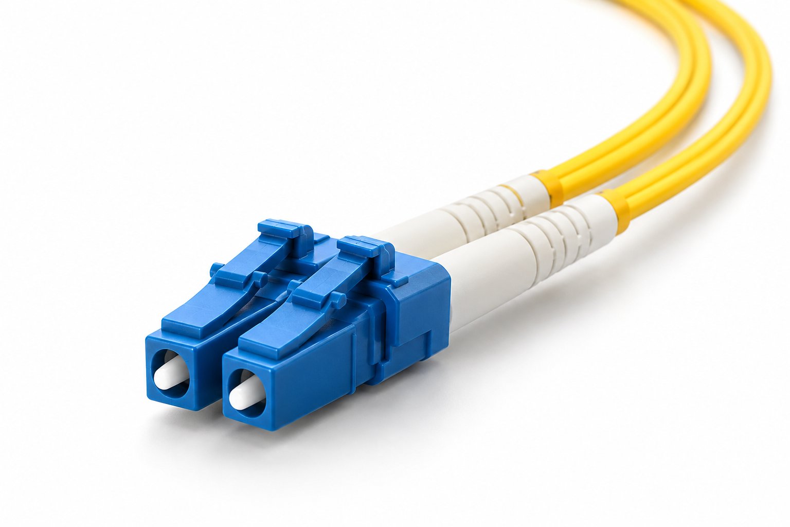
The parameters above can look like a wall of acronyms if your team has not ordered cords recently. Our guide on how to read fiber optic patch cord specs — insertion loss, return loss and polish types walks through each value and what it means on the test report. The reference product for this application is the LC-LC duplex single mode patch cord, assembled and labelled as a matched transmit/receive pair — which brings us to polarity.
Polarity and Duplex Planning on a Two-Fiber Link
A two-fiber fronthaul link is a simple loop: the radio transmits on one fiber and receives on the other, and the BBU does the same in the opposite direction. For that loop to close, the fiber that carries TX at one end must arrive as RX at the other. A duplex cord that crosses the pair when it should not — or that is straight-through when the port convention expects a cross — swaps TX and RX, and the link simply does not come up. There is no partial degradation, no error counter to chase: the transceivers never see each other. On a tower-top radio this failure is discovered late, when crews are already on site, and the fix is swapping cords that were supposed to be final.
The practical controls are threefold. First, order duplex cords that are factory-built and labelled as matched TX/RX pairs rather than two singles pulled from a bin; the LC-LC duplex construction referenced above exists for exactly this reason. Second, decide the site's polarity convention before procurement — A/B method, straight-through or crossed — and document it on the installation drawings so every cord in every position is ordered to the same rule. Third, mark cords at both ends with the position they serve; colour and label discipline at the ODF pays for itself the first time a sector needs troubleshooting at night. Polarity mismatches are entirely preventable with a convention written down once, and they are a common avoidable cause of a failed first bring-up.
UPC or APC: Match the Equipment, Not a Preference
UPC versus APC is not a quality question — it is a compatibility question. The two polishes have different physical geometries (an angled versus a flat ferrule end-face), and a UPC connector mated into an APC adapter or port will not make optical contact correctly: the ferrules touch at an angle that leaves an air gap, resulting in high insertion loss, poor return loss, and physical damage to the end-faces. The rule is simply that each mated interface must use one polish throughout, and that polish must match what the equipment manufacturer built into the port. Most 5G fronthaul radio and BBU ports follow the equipment vendor's convention — many use LC UPC, some specify APC on certain interfaces — so check the radio and BBU hardware documentation before ordering anything.
Where conventions differ on the two ends of the same span — for example an APC port at the radio and UPC patching at the ODF — the transition must happen at a designed conversion point, not at a random adapter. Using the wrong polish adapter as an unintended conversion is the classic silent-fault mistake. Adapters are available in both polishes for exactly this planning purpose: the LC/UPC duplex fiber optic adapter and the LC/APC duplex fiber optic adapter should appear on the bill of materials in the quantities that match your convention, clearly separated. If the distinction feels fuzzy, our article on UPC versus APC connectors and which to choose covers the geometry and the decision rules in detail. The one-line takeaway: match the equipment on each interface, plan any polish conversion deliberately, and never mix the two within a single mated pair.
Installation Practice on the Tower
Installation practice determines whether a cable that passed factory testing survives a decade of wind and weather. The first discipline is bend radius. For the outdoor loose tube construction described earlier, the minimum radius is 20 times outside diameter while installing and 10 times outside diameter in service — for a typical mid-count build this means a careful hand around every corner during the pull, and enough slack at corners and terminations that the resting radius never collapses below the service limit. Tight bends at the tower base or inside a radio bracket can push fiber attenuation up locally, and a bend that is marginal on install day can open into a macro-bend problem as the jacket ages and the cable moves under wind load.
Pulling tension follows the same logic. The cable's short-term and long-term tensile ratings by core count were covered in the earlier construction section; the field rule is to keep pulling well inside the long-term rating, use a pulling grip or breakaway swivel on longer runs, and pull from drums positioned so the route does not force double-handling. Where the last span is on a pole line, the self-supporting figure-8 construction is the appropriate choice rather than pulling a standard loose tube cable to a tension it was not designed for. Our contractor's guide to cable pulling without exceeding tension and bend limits covers the mechanics step by step.
Fixing and environmental load are professional-practice territory rather than catalog numbers, but a few rules hold across sites: space clamps and hardware so the cable carries no unsupported weight between fixings, respect the jacket's UV rating by using outdoor-rated fixings and never re-using indoor hardware outdoors, and leave slack loops at the tower base and top sized for re-termination. At both ends, terminations belong in proper closures or boxes: our splice closure and slack storage guide explains why closure selection and slack management drive long-term reliability as much as the cable itself. Finally, clean and inspect every connector end-face before mating — every time, including factory-terminated cords arriving in sealed bags. Dust and residue are among the largest causes of connector loss on site, and the connector cleaning and inspection guide gives the standard procedure.
Testing and Acceptance on Site
Acceptance testing closes the gap between the factory test report and what the installed link actually delivers. The baseline method is insertion loss measurement with a light source and power meter: set a reference, measure each fiber end to end against the loss budget, and compare the result with what the budget predicted given the span length, splice count and mated connector pairs. If a link measures above its calculated value, the excess is usually at a connector — dirt, a damaged ferrule or a bad polish — and the fix is cheap if found at acceptance and expensive if found after the sector is live. The full procedure is covered in our article on testing a fiber optic link with a light source and power meter.
An OTDR trace belongs in the acceptance package for every outdoor span. Beyond confirming overall loss, the OTDR characterizes the span position by position — splice losses, connector reflections, and the true length of each fiber — which turns it into the fault-location tool for the rest of the site's life. When a tower-top jumper fails two years later, the archived baseline trace is what lets the crew distinguish a damaged splice from a wet closure from a broken fiber before anyone climbs. Our guide on using an OTDR to accept a new fiber optic cable installation covers the settings and record-keeping. For short jumpers and quick connector checks, a visual fault locator is the fastest tool on the tower: a visible break or a bright bend-scatter point identifies the problem in seconds. See the VFL troubleshooting guide for typical uses.
Keep records at two levels. At incoming inspection, hold the factory test data for each cable drum and cord batch alongside the delivery paperwork. At site acceptance, record per-fiber insertion loss results and OTDR traces, tied to fiber and position identifiers. Those two document sets together are what a warranty claim or a maintenance investigation will be built on.
Ordering, Lead Time and Warranty for FTTA Cable and Cords
Commercial planning for a FTTA order comes down to three families with different minimums and cycles. For outdoor G.652D loose tube cable, the reference minimum order is 10 km per order for standard core counts and 20 km for custom core counts, with typical dispatch 15 to 20 working days after order confirmation. Standard drum lengths are 2 km, 4 km and 6 km on wooden drums, so a multi-site project can be planned around drum lengths that match or exceed its longest spans rather than introducing mid-route joints for convenience. Armored cable, for routes that need the higher mechanical protection, carries a reference MOQ of 2,000 m per configuration with lead time of 10 to 25 working days depending on configuration.
Patch cords are the fastest-moving item: reference MOQ is 100 pcs per configuration, packing is 100 pcs per inner bag and 1,000 pcs per carton, and standard lead time runs 7 to 15 working days, extending to 15 to 25 working days for mixed or high-volume orders. Because a FTTA project typically orders several cord configurations — different lengths, jackets and polish types across the site — the mixed-order lead time is often the realistic planning number, and it is worth aligning the cord delivery with the cable delivery so one site crew can complete termination and testing in a single mobilization.
Two caveats belong in any procurement plan. First, these MOQs and lead times are planning references; the binding figures are those confirmed with the quotation for your specific configuration, and our MOQ and lead time article explains how configuration choices move both. Second, warranty terms: all three product families carry a warranty of 12 months from shipment date, and it is worth reading the warranty guide to understand what that period covers in practice — and the damage and repair planning guide for how to act if cable is damaged in transit or on site, since documented inspection at receipt is part of any claim.
A Pre-Order Checklist for FTTA Cable and Patch Cords
Before the purchase order goes out, the following items should each have a written answer. Anything left blank becomes a site-day problem later.
| Item | What to confirm |
|---|---|
| Route length and construction | Measured route per site, construction type (loose tube, armored, or figure-8 self-supporting on the pole span), drum lengths matched to spans |
| Fiber count | Current fronthaul demand plus documented spare capacity per cable |
| Armor type | Steel tape or steel wire, justified by route exposure and rodent risk; tensile and crush ratings confirmed against the datasheet |
| Fiber type | ITU-T G.652D single mode across cable, pigtails and cords — one fiber type end to end |
| Polish type and polarity | UPC or APC per equipment port convention; site polarity method documented; duplex cords ordered as matched labelled pairs |
| Cord lengths and jacket | Lengths measured on the real run plus service loops; LSZH or PVC jacket; 2.0 mm or 3.0 mm OD |
| Loss limits | Insertion loss release limit and return loss per cord stated on the order; site loss budget documented with acceptance targets |
| MOQ and lead time | Reference MOQs and lead times confirmed with the quotation for your exact configuration |
| Packing and marking | Drum lengths and marking per cable; cord packing (100 pcs per inner bag, 1,000 pcs per carton) and end labels matched to positions |
| Warranty terms | 12 months from shipment date for all product families; receipt inspection procedure agreed |
Frequently Asked Questions
Can standard indoor patch cords be used on the exposed tower-top span? No. Indoor cords are not built for continuous UV exposure, wide temperature swings or wind-induced movement, and their jackets and constructions will degrade on an exposed tower. The exposed portion of the link belongs in outdoor-rated construction; factory-terminated outdoor-suitable cords or pigtail transitions inside a closure are the appropriate way to reach the radio ports.
How much spare fiber should a site carry? A common professional planning approach is to size the cable for current fronthaul links plus a documented spare margin — often a meaningful fraction of the fiber count rather than one or two fibers — and to pair it with a spare-cord stock kept in the site's maintenance kit. The right margin depends on sector growth plans and how expensive an after-commissioning visit to the tower is on your site class; a short, hard-to-access structure justifies a larger margin than a rooftop with easy access.
Can one cable serve both fronthaul and a future sector expansion? Yes, and this is precisely why fiber count is chosen above immediate demand. Additional sectors or additional radios on the same structure reuse fibers in the same outdoor cable, with new pigtails or cords terminated at the closure or ODF. What this requires is spare fibers protected in the closure design and slack storage from day one, so the expansion is a termination job rather than a new pull.
What jacket should tower-bound cords use? For cords that spend any of their run exposed, a UV-stable outdoor-suitable jacket is the starting point; where the cord passes through indoor spaces or enclosed equipment rooms on its way to the BBU, LSZH offers a low-smoke, halogen-free option that many site standards require indoors. Where the cord is entirely indoors, either LSZH or PVC is acceptable per the site standard. Match the jacket to the environment each cord actually traverses rather than to a single site-wide default.
Are custom cord lengths practical at project quantities? Yes. Custom lengths from 0.5 m to 30 m are available within the standard 100 pcs per configuration MOQ, so a project can order, for example, 2 m radio-port cords and 15 m base-run cords as two configurations at practical quantities. The practical constraint is configuration count: each distinct length, jacket and polish combination is its own configuration, so consolidating a site into a small set of standard lengths keeps both ordering and spares simple. Mixed or high-volume cord orders carry the 15 to 25 working-day lead time, which should be planned into the site schedule.
What paperwork should accompany a FTTA cable order? Three sets. First, factory test data: per-drum cable test records and per-batch cord insertion loss and return loss measurements — every cord passes connector end-face inspection, insertion loss and return loss measurement before packing, and the records should ship with the goods. Second, delivery documentation tying drums and cord cartons to the purchase order, with drum markings that identify construction, fiber count and length. Third, the commercial documents stating warranty terms of 12 months from shipment date. Together these are the baseline for incoming inspection, site acceptance and any later claim.
Plan Your FTTA Cable and Patch Cord Order
Tell us your route, fiber count, armor and termination requirements, and we will confirm the matching construction, lead time and packing plan for your site.
Request FTTA Cable Details