
A buyer's guide to choosing fiber optic cable for harsh environments: operating temperature, water blocking, UV resistance, corrosion, and a route-to-construction decision map for outdoor projects.
Why the Environment Decides Your Fiber Optic Cable Specification
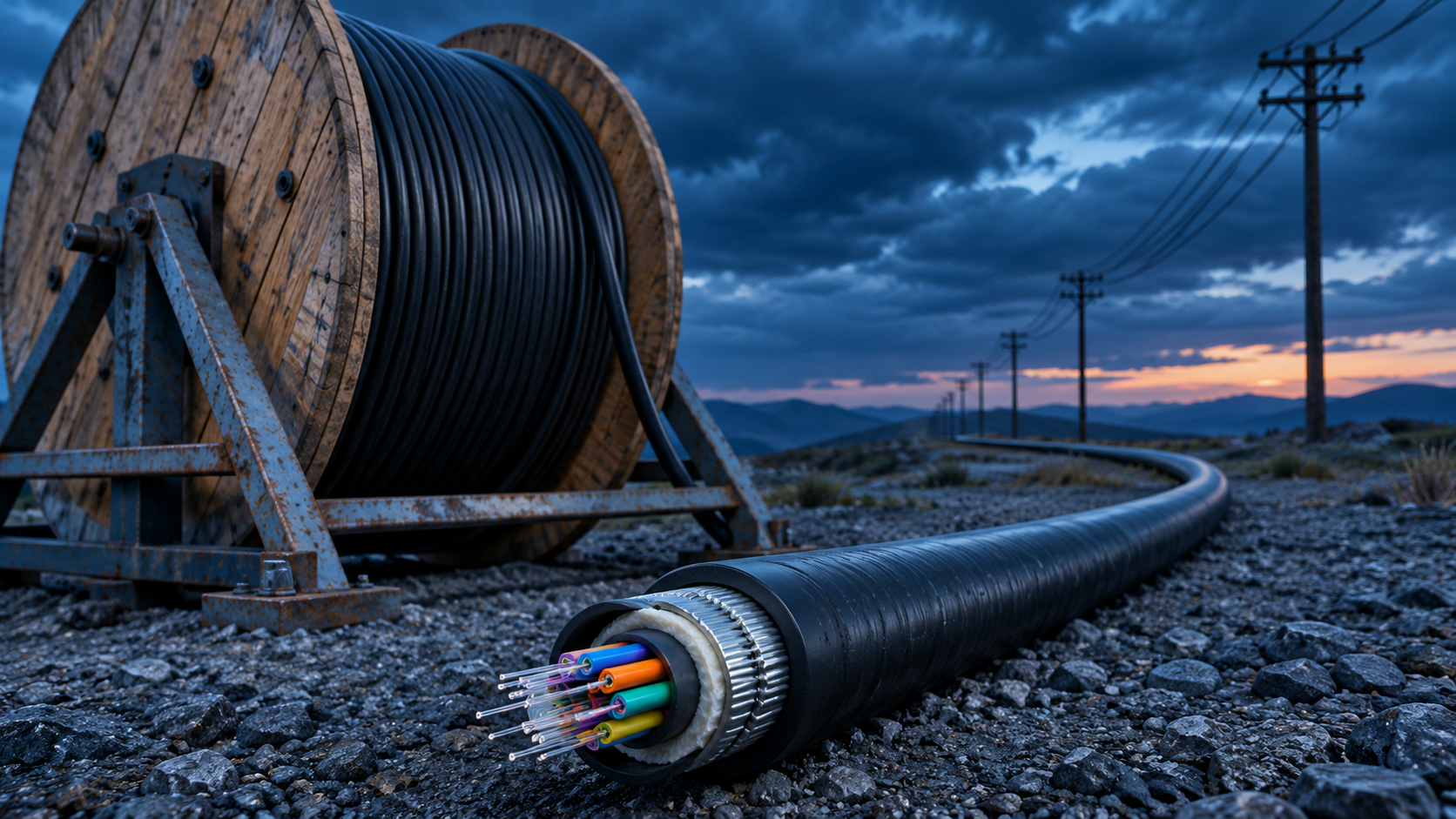
If you manage an outdoor fiber build, the route will face heat, cold, water, sunlight, soil chemistry, and mechanical load for fifteen years or more. No single cable construction handles all of that equally well. Your job as a buyer is to decide which stresses dominate on your route and to confirm, line by line on the datasheet, that the cable you order addresses them.
The economics push you toward that decision. Cable is one of the cheapest line items on an outdoor route. Trenching, duct installation, pole work, and splicing dominate the budget. When a cable fails in the ground or on a pole, the repair cost is mostly civil work and crew time, not the replacement reel. A cable that survives the environment for its full design life is therefore worth more per meter than a cable that is cheaper on paper but needs attention mid-life.
This guide breaks the selection problem into the environmental factors that actually decide outdoor cable performance: temperature, water blocking, UV resistance, corrosion, and mechanical load. For each one, we explain the mechanism, what to look for on a datasheet, and the questions to put to your supplier before you confirm an order.
The Five Environmental Stress Factors That Kill Outdoor Fiber Optic Cable
Outdoor cable rarely fails because the glass breaks. It fails because the environment attacks the construction around the glass until the fiber is bent, wet, or strained beyond its limits. Five stress groups cover most of those failure paths:
- Temperature cycling. Daily and seasonal swings expand and contract the jacket, tubes, and strength members at different rates. Over years, that differential movement can push fiber into microbends and raise attenuation, especially at temperature extremes.
- Water ingress. Water that enters a cable jacket travels longitudinally through the core if nothing blocks it. Water in contact with fiber or in frozen form inside the core is a leading cause of long-term degradation in buried and duct cable.
- UV exposure. Sunlight degrades jacket materials that are not formulated for outdoor use. Aerial cable and cable in exposed duct entries need UV-resistant jackets, typically black PE.
- Corrosion and chemical exposure. Salty coastal air, acidic or alkaline soils, and contaminated ground attack metallic elements and jacket compounds. Cable near power infrastructure also faces induced voltage on any continuous metal path.
- Mechanical load. Crush from soil and traffic, impact from rocks and tools, rodent chewing, and — on aerial routes — wind, ice, and sag all load the cable. Rodent damage on buried cable concentrates in the first 300–600 mm of cover, which is one reason armor placement matters.
Each factor maps to specific datasheet lines. The sections below work through temperature in detail first, because it interacts with every other stress — and because it is the factor buyers most often misread.
Operating Temperature: What -40 C to +70 C Actually Means for Your Route
Most outdoor single mode cable datasheets list a typical operating temperature range of -40 C to +70 C. Nexora's Outdoor G.652D Single Mode Fiber Optic Cable, for example, lists a typical operating temperature of -40 C to +70 C, alongside loose-tube gel-filled construction, 2–288 cores, and a black PE outer jacket. Treat that range as a typical industry value, and confirm the exact figure on the datasheet supplied with your order before you commit to a route design.
Two points about what the rating means. First, it describes the conditions under which the cable is designed to keep performing — not a promise that performance stays identical across the whole range. Attenuation at -40 C is not the same as attenuation at +25 C, and a good datasheet will let you see how much it changes. Second, the rating covers the cable, not the installation. A cable pulled too tight in July will have a different stress profile in January, regardless of its rating.
What thermal cycling does to a loose-tube cable
A loose-tube cable contains materials with different thermal expansion rates: the PE jacket, the tube stranding around the central strength member, the gel, and the fiber itself. When the cable heats up, the jacket expands more than the steel or FRP strength member inside. When it cools, the jacket contracts. The fiber inside each tube is deliberately left slightly longer than the tube path, a construction called fiber overlength, so that contraction does not tension the glass. But if the design margin is thin, or if the cable was installed with the fiber already displaced toward one end of the tube, extreme cold can pull the fiber against the tube wall. That contact creates microbends, and microbends raise attenuation.
At the hot end, the risks are different. Sustained high temperature softens jacket and gel behavior and can change the geometry of the tube stranding. Combined with water already present in the core, heat accelerates aging of the materials around the fiber.
The practical consequence for a buyer: temperature rating is a starting point, and temperature-cycle test behavior is the real decision data. Ask the supplier what attenuation change their cable shows over a full temperature cycle, and ask for the test conditions in writing. Do not assume a rating printed on a website includes cycle data.
Mapping your climate to the rating
A rating of -40 C to +70 C is a range, not a guarantee of suitability. What matters is where your route's extremes sit inside that range, and how fast it moves between them. Use the table below as a checklist of what to confirm on the datasheet for each climate type:
| Climate type | Dominant stress | What to confirm on the datasheet |
|---|---|---|
| Hot-arid (desert, high heat, large day-night swings) | Sustained high temperature plus rapid daily cycling and UV load | Upper temperature limit against your peak ground and duct temperatures, attenuation change over a full cycle, and UV-resistant jacket specification |
| Cold-continental (hard winters, deep freeze) | Extreme low temperature and freeze-thaw cycling; water in the core freezing | Lower temperature limit against your record lows, water-blocking construction detail, and low-temperature attenuation data |
| Tropical-coastal (heat, humidity, salt air) | Continuous humidity, water ingress risk, corrosion of metallic elements | Water-blocking construction in tube and core, jacket material for long-term wet exposure, and whether any metal member needs corrosion protection on your route |
| Temperate (moderate swings) | Standard outdoor exposure; mechanical and water stresses usually dominate over temperature | That the typical -40 C to +70 C range still covers your local extremes, plus the mechanical parameters for your installation method (direct burial, duct, or aerial) |
One more climate-related note: duct routes in hot regions can run hotter than ambient air, because dark duct and conduit absorb sun at access points and the duct itself traps heat. If your route runs through surface duct in a hot-arid region, size your temperature requirement against duct conditions, not weather-station air temperature.
Questions to put to your supplier
Before ordering, put these three questions in writing:
- What is the operating temperature range printed on the datasheet for the exact configuration and core count I am ordering?
- What attenuation change does the cable show over a temperature cycle test, and under what test conditions?
- Which construction features (fiber overlength, tube stranding type, strength member material) support the rating on my route's temperature profile?
The third question matters because core count changes the construction. A 288-core cable has more tubes stranded around the strength member than a 24-core cable, and the thermal behavior of that structure is a design property. Our guide to how to read a fiber optic cable datasheet before you buy walks through the datasheet lines that answer these questions.
Temperature and Your Loss Budget: Why Attenuation Drifts
Every optical link design starts with a loss budget: the total attenuation the link can absorb and still meet the receiver's requirements. The attenuation figure you use to build that budget comes from the datasheet. For single mode cable, datasheets commonly list typical values of <=0.36 dB/km at 1310 nm and <=0.22 dB/km at 1550 nm, measured against a reference test method such as IEC 60793-1-40. Nexora's outdoor and armored cable datasheets list these as typical figures, and the same caveat applies across the industry: the number is typical, and the datasheet supplied with your order governs.
The critical detail buyers miss: that attenuation figure is measured at reference conditions — standard laboratory temperature, on a straight, unstrained length of cable. Your route will never match those conditions. It will run hotter and colder, and it will carry the residual strain of installation. Temperature is one of the reasons the attenuation on your deployed link will drift above the datasheet value.
The mechanism of temperature-related attenuation drift
Three mechanisms drive the drift:
- Microbending from thermal movement. As described above, differential expansion between jacket, tubes, and strength member can press fiber against the tube wall at temperature extremes. Microbends scatter light and raise attenuation, and the effect concentrates at the cold end of the range on loose-tube designs.
- Residual installation strain. A cable installed near its tension or bend limits carries stored stress. Thermal cycling redistributes that stress over time, and fiber that was marginally strained at installation can develop higher attenuation after seasons of movement.
- Water interactions. Water in the core changes the thermal and mechanical behavior of the materials around the fiber. Freezing water expands and can distort tube geometry; this is one reason water blocking and temperature rating must be evaluated together, not as separate checklist items.
The direction of the effect is consistent: deployed attenuation runs above the datasheet value, not below it. The datasheet number is your baseline, not your design number.
How to handle it in the loss budget
For every link on your route, add a temperature allowance as a design margin on top of the datasheet attenuation, splice losses, and connector losses. The size of that margin should reflect your climate and your construction: routes with wide temperature swings and long loose-tube runs need more margin than short temperate duct runs. Do not borrow a fixed margin value from another project; derive it from the temperature-cycle data your supplier provides for the specific cable you are buying. Our guide to calculating a fiber optic link loss budget shows where that allowance sits in the full budget structure.
Two checklist items follow from this:
- Request temperature-cycle attenuation data before the order is final, not after. If a supplier cannot provide it for the configuration you are buying, treat the operating temperature range as unverified for your route.
- Verify against the datasheet, not the website. Product pages summarize typical values. The datasheet supplied with your order is the document your design should reference. Every reel from Nexora is attenuation and continuity tested before dispatch, with a test report available on request, so you can check the shipped cable against the baseline you designed to.
Temperature is the first of the five environmental factors, but it is not the one that does the most damage on most routes. Water ingress and mechanical load destroy more outdoor cables outright. The next sections cover water blocking and UV resistance, then corrosion and mechanical load, so you can score your route against all five before you shortlist a construction.
If you already know your route needs a general-purpose outdoor loose-tube design, the Outdoor G.652D Single Mode Fiber Optic Cable product page lists the construction details discussed here: gel-filled loose tubes, a steel wire or FRP strength member, black PE jacket, and direct burial, duct, or aerial deployment. For routes where rodents, crush, or impact dominate over temperature, see the armored cable guide later in this article.
Water Blocking: How Gel-Filled and Dry-Core Constructions Stop Longitudinal Water Travel
Water finds a cable through two paths. The first is through the sheath itself: a nick, a rodent bite, a shovelful of rock at backfill. The second is at the ends, where closures, pigtails, and building entries meet the cable. A sound jacket handles the first path. Water blocking handles the second.
The concern for a buried route is longitudinal water travel. When moisture enters through a damaged point in the sheath, it does not stay where it entered. Pressure differences, gravity, and temperature gradients push it along the cable, usually toward the lowest point or the nearest closure. Over tens or hundreds of meters, water in the wrong place can reach splice trays, degrade connectors, and change the attenuation of the fiber itself. On a long buried run, the entry point may be hundreds of meters from the point where your OTDR first shows a problem.
Nexora's outdoor G.652D loose-tube cable uses two barriers working together. The first barrier is gel inside each loose tube. The gel fills the space around the fiber and blocks water from moving along the tube. The second barrier is water-blocking material in the cable core, around and between the tubes. If water passes the jacket and the armor, it still has to get through both barriers before it can travel far along the cable. A single-barrier design fails completely if that one barrier is breached. A two-barrier design degrades slowly and locally instead.
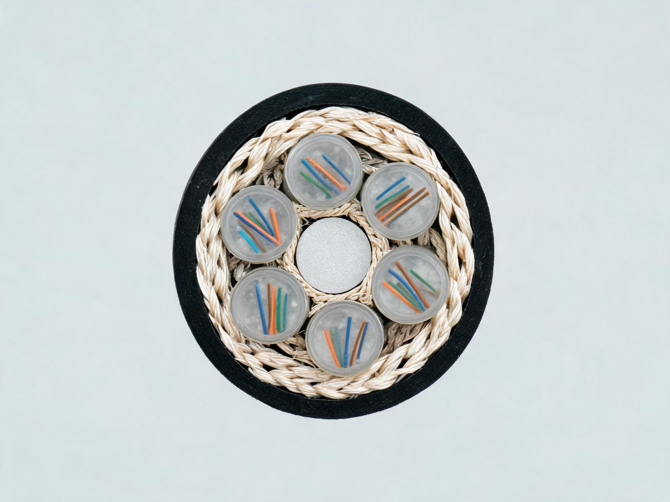
The end face tells you what you are buying. Gel-filled tubes, aramid yarn, and a central strength member all visible in one cross-section. When you audit a sample before a large order, cut a short length and look at it. Gel should fill the tube, not sit in a bead at one end. Water-blocking yarn or tape should be present in the core, not replaced with plain filler.
Why Water Damage Surfaces Months Later
Water ingress rarely shows up as an immediate failure. A nicked jacket lets water in, the water travels a few meters, and nothing visible happens. The fiber keeps transmitting. Over weeks and months, moisture around the fiber changes attenuation, especially at 1550 nm where water peak effects and microbending sensitivity are greatest. Splices in a wetted closure can show rising loss. By the time a link drifts out of its loss budget, the physical entry point may be far from the measurement point, and locating it costs crew time on a buried route.
This is why the water-blocking spec matters more for direct burial than for indoor runs. In a building, a breach is visible and accessible. Under a field or a road, the cable has to contain the water itself for the life of the link. For guidance on what happens after burial, see Nexora's guide on installing direct buried fiber optic cable.
Gel-Filled Versus Dry-Core: What a Buyer Should Compare
Both constructions appear in outdoor cable. Gel-filled loose tube is the traditional approach: gel in each tube plus water-blocking material in the core, which is what Nexora's outdoor G.652D cable specifies. Dry-core designs replace tube gel with water-swellable tapes and yarns throughout the core. Each has practical consequences at splicing, handling, and maintenance stages, summarized below.
| Buyer-relevant dimension | Gel-filled loose tube | Dry-core (water-swellable) |
|---|---|---|
| Water blocking mechanism | Gel physically fills and seals each tube; core material adds a second barrier | Swellable tapes and yarns expand on contact with water to block travel |
| Splicing and preparation work | Gel must be cleaned from fiber before stripping and splicing; adds handling steps | No gel cleanup; faster preparation, but confirm swellable material does not complicate re-entry |
| Handling and cleanliness on site | Gel transfers to gloves, tools, and closures; crews need wipes and solvent | Cleaner to handle; easier for crews working multiple closures in a day |
| Long-term water containment | Gel does not wash out or deplete; containment is passive and permanent | Performance depends on the swellable material; verify test basis with the supplier |
One rule applies regardless of construction: ask the supplier which IEC 60794-1 water penetration test their water-blocking data references, and confirm the referenced values on the datasheet supplied with your order. Do not accept a datasheet line that says "water blocked" without a test reference behind it. If you need help decoding test references, see Nexora's guide on reading a fiber optic cable datasheet before you buy.
Water blocking is only one layer. The armor and jacket around it decide how much water ever reaches the core, which is the subject of the next two sections.
The Jacket Is the First Barrier: PE versus Other Sheath Materials
Everything above the water blocking depends on the outer sheath holding. On Nexora's outdoor constructions, the outer jacket is black PE, which resists UV, abrasion, and water ingress. That single sentence carries three separate requirements for an outdoor cable, and it is worth unpacking each one before you compare quotes.
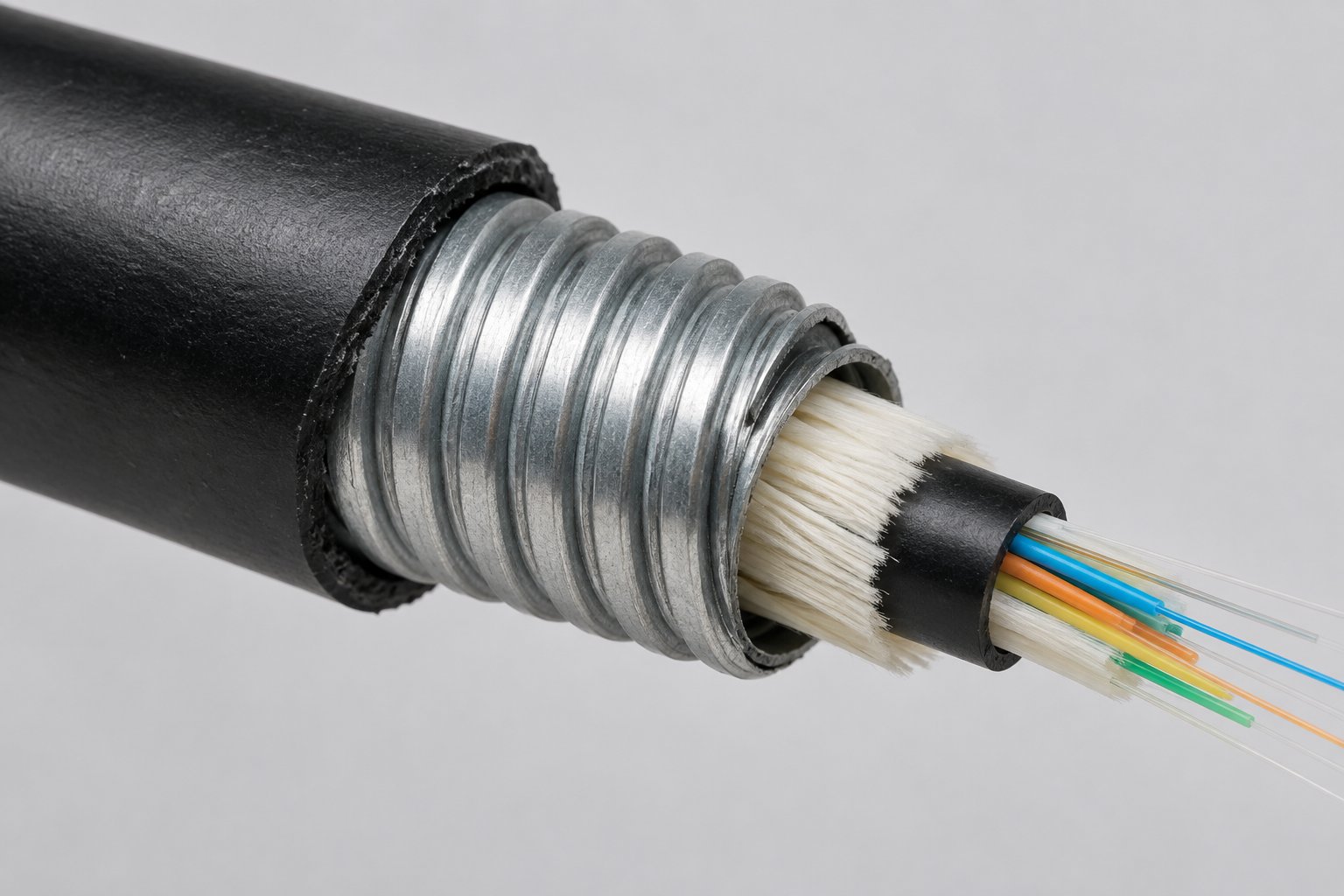
The cross-section shows the order of barriers clearly: black PE jacket on the outside, corrugated steel tape armor beneath it, then the cable core. Water has to defeat the jacket, then the armor, then the core water blocking before it reaches the fiber. Each layer has a job.
What the Jacket Does for Buried Cable
For direct burial, the jacket's main jobs are abrasion resistance and water ingress resistance. Backfill is not gentle. Sharp stones, compacted soil, and ground movement abrade the sheath over years. A jacket that scuffs easily thin spots early, and a thin spot is a water entry point. In duct runs, the jacket also handles friction against duct walls during the pull. If you are specifying burial, read the trenching and backfill guidance in Nexora's direct burial installation guide, because installation practice determines how much stress the jacket actually sees.
What the Jacket Does for Aerial Cable
For aerial runs, the jacket's dominant job changes: it faces continuous UV exposure for the life of the cable, plus wind loading and temperature cycling. This is why both Nexora's ADSS cable and figure-8 self-supporting cable specify a UV-resistant black PE jacket suited to long-term outdoor exposure. On a pole line, the jacket is not a buried protective layer you never see again. It is a weather-exposed surface, and its formulation decides whether it chalks and cracks in five years or holds for decades. Nexora's ADSS article on choosing ADSS for an aerial network covers how span and loading interact with that jacket requirement.
Where Armored Construction Fits
When the route includes rodent pressure, crush risk, or mechanical abuse, the jacket alone is not the barrier that does the work. Steel tape or steel wire armor between the core and jacket takes the crush and impact load and forms a continuous metal barrier against burrowing rodents. The PE jacket over the armor still resists water and UV, but the armor decides whether a gopher or a backhoe edge reaches the core. For the full decision logic, see Nexora's buyer guide on when to use armored fiber optic cable, and the armored fiber optic cable product page for constructions from 4 to 288 cores. Rodent damage, note, concentrates in the first 300-600 mm of cover, which is exactly the zone the armor protects.
One construction note that catches buyers out: armored cable is not an aerial construction. It should not be strung on poles or left exposed to sustained UV and wind loading. For poles, use ADSS or figure-8, both built for that exposure.
UV Resistance: Why Indoor Cable Fails Outdoors
UV radiation degrades polymer jackets. Unprotected plastics exposed to sunlight lose flexibility, chalk on the surface, and eventually crack. A cracked jacket stops being a water barrier and stops being an abrasion barrier at the same time, so UV damage on an exposed run opens the door to every failure mode in the previous sections. The damage is cumulative and invisible until the surface fails, which is why it is easy to underestimate at specification time.
Outdoor constructions solve this with UV-stabilized black PE. Carbon black in the PE is what gives outdoor cable its familiar black color and blocks UV from reaching the polymer structure. Nexora's outdoor G.652D cable, ADSS cable, and figure-8 cable all specify black PE jackets with UV resistance stated in the construction. On long aerial runs, the ADSS datasheet notes that the UV-resistant PE jacket reduces maintenance attention, which is a maintenance-cost argument as much as a reliability argument: a jacket that holds means fewer mid-span sheath repairs over the cable's life.
The Specification Error to Avoid
Indoor cable is not built for this exposure. Tight-buffered and distribution constructions are jacketed for indoor handling, fire performance, and bend behavior, not for years of direct sunlight. Running an indoor construction outside, even on a short exposed span between buildings or along a rooftop, is a specification error: the jacket will degrade, the degradation will crack it, and the failure will look like a mysterious link problem months later. Specify indoor cable for riser, plenum, and horizontal runs, and outdoor constructions for anything that crosses the wall. If fire performance is the reason you are looking at indoor jackets, Nexora's article on what LSZH fiber optic cable is and when to specify it explains that trade-off. For indoor selection by run type, see the guide on choosing indoor cable for riser, plenum, and horizontal runs.
Be equally careful at the transition. Short exterior jumpers and temporary runs are where indoor cable ends up outdoors by accident. Treat any segment that sees daylight as an outdoor cable segment, regardless of length.
Corrosion and Salt: Choosing Metal or Metal-Free Constructions for Coastal and Industrial Routes
Steel is a strength and protection material, but it is also conductive metal sitting in your route environment. In coastal high-salt air, saline soil, or industrial areas with chemical exposure, steel armor and steel messengers face corrosion over the cable's life. In lightning-prone areas, conductive metal in the cable adds an induced-voltage path that your grounding design then has to manage. Neither problem makes metal constructions wrong. Both make them a choice you should make deliberately, route by route.
Mapping the Route to the Construction
Start with the soil and air along the route, not with the cable catalog. Three conditions should move you toward metal-free options:
- Coastal high-salt routes. Salt spray and saline soil attack exposed steel. On an aerial figure-8 run near the coast, the metal-free FRP messenger option may be preferable: it is lighter, contains no metal, and reduces induced-lightning risk. FRP has lower tensile than steel strand, so confirm span capability against your pole spacing on the datasheet supplied with your order. The figure-8 self-supporting cable product page covers both messenger options, and Nexora's article on deploying figure-8 self-supporting cable walks through the steel versus FRP decision.
- Lightning-prone areas. A steel messenger or steel armor is a conductive path along the route. Where strike probability is high, every conductive member needs bonding and grounding planning. A metal-free construction removes the path entirely: ADSS is all-dielectric, with an aramid yarn strength member and no metal anywhere, so there is no bonding or grounding needed at supports and no conductive path to design around. That simplifies installation on power-shared pole lines and in strike-exposed terrain. See the ADSS fiber optic cable product page and Nexora's article on whether ADSS is the right choice for your aerial network.
- High water table, saline soil, and chemical plant perimeters. Buried steel armor in wet, salty, or chemically aggressive soil corrodes from the outside in once the jacket is breached. Here the decision is not always "no metal." Steel armor remains the strongest answer to rodent and crush loads, and on many industrial routes the mechanical threat outweighs the corrosion concern. The practical approach is to map the specific soil conditions and decide per segment: full steel-wire armor where crush and rodent risk dominate, lighter or dielectric constructions where corrosion dominates. Ask each supplier how their armor and jacket system is specified for the soil class on your route, and confirm the answer against the datasheet supplied with your order.
Putting the Four Dimensions Together
Water blocking, jacket material, UV resistance, and corrosion behavior are not independent checkboxes. They are layers of one containment system. A buried cable in saline soil needs gel-filled two-barrier water blocking, an abrasion-resistant black PE jacket, armor sized to the route's mechanical threats, and a corrosion decision made consciously. An aerial cable across open country needs UV-stabilized PE, a dielectric or grounding-planned messenger, and water blocking sufficient for closure-level ingress. Specify the layers as a set in your RFQ rather than one at a time; Nexora's article on what to include in a fiber optic cable RFQ shows how to put the route conditions in front of the manufacturer so the construction comes back matched to them.
Matching the Construction to the Route: A Decision Map for Harsh-Environment Projects
A harsh-environment cable order starts with the route, not the datasheet. The route decides which construction family you specify, and the datasheet then decides whether a specific build within that family survives the job. Buyers who reverse this order — pick a cable first, then hope the route cooperates — usually discover the mismatch during pulling or burial, when changes are expensive.
Four route archetypes cover most outdoor utility and ISP work. Match your project to one of them, then confirm the listed datasheet items before you commit to a configuration. Every number in this section is a typical industry value, not a guarantee; always confirm on the datasheet supplied with your order.
Route 1: Direct Burial Through Rocky or Rodent-Prone Ground
Where the route runs through rocky soil, farmland with burrowing rodents, or an industrial right-of-way, specify an armored fiber optic cable. Steel tape or steel wire armor sits between the cable core and the outer PE jacket. The armor takes crush and impact load and forms a continuous metal barrier against burrowing rodents.
The choice between the two armor types comes down to tensile load. Typical short-term tensile for a steel tape build runs up to 3,000 N; a steel wire build reaches up to 6,000 N. Crush ratings follow the same pattern, with typical values up to 3,000 N/100 mm for steel tape and 4,000 N/100 mm for steel wire. If your civil method involves heavy pulling through shallow conduit sections or ground that shifts under load, the steel wire option carries the higher margin. Confirm both ratings on the datasheet for the core count you plan to order, because these values vary with cable diameter and construction.
Note one boundary on this family: armored cable is not an aerial construction. It should not be strung on poles or left exposed to sustained UV and wind loading. If part of your route mixes buried and aerial sections, plan a transition point.
Burial practice matters as much as the cable spec. Depth, bedding, and backfill determine how much of the armor rating you actually get to use; the direct burial installation guide covers trenching and backfill in detail.
Route 2: Duct and General Outdoor Backbone
For duct runs and general outdoor backbone where rodents and direct crush are not the dominant risk, a loose-tube gel-filled outdoor cable with G.652D fiber is the standard starting point. Constructions span 2 to 288 cores, with a steel wire or FRP strength member and a black PE jacket that resists UV, abrasion, and water ingress. Gel in the tubes blocks longitudinal water travel, and water-blocking material in the cable core adds a second layer.
This family deploys direct burial, duct, and aerial, but its typical short-term tensile of 1,500 to 2,700 N by core count — about 20 to 25% lower for FRP builds, tested to IEC 60794-1-21 — means you should check the pulling plan before choosing it for anything beyond duct work. Typical bend radius is 20x OD during installation and 10x OD in service; exceeding either during a pull risks attenuation that an OTDR will catch later. The pulling tension and bend limits guide explains how contractors keep a duct pull inside those limits. See the outdoor G.652D loose-tube cable product page for the configuration range.
Route 3: Aerial on Power Lines
When the route follows power lines, all-dielectric ADSS is the family that removes the electrical problem entirely. Aramid yarn carries the mechanical load; there is no metal and therefore no conductive path, so no bonding or grounding is needed at supports. The UV-resistant black PE jacket is designed for long-term sun exposure and reduces maintenance attention on long aerial runs.
The datasheet items to confirm are span-related, not electrical. Standard ADSS builds support typical spans up to 100 m, and reinforced builds up to 300 m — but span capability depends on wind and ice loading, sag limits, and conductor clearance at your specific site. A span that works in calm conditions can fail the sag check under design ice load. Installation tension is typically limited to not more than 20% of the rated tensile strength, so the winch plan needs that figure before mobilization. Typical operating temperature is -40 °C to +70 °C, consistent with the other outdoor families here.
Route 4: Aerial on Telecom Poles with Wide Spans
On telecom pole lines with wider spans, a figure-8 self-supporting cable places an integrated steel strand or FRP messenger alongside the optical core in one figure-8 profile. The messenger carries the mechanical load, so the fiber core is not tensioned directly — a structural advantage over lashing loose cable.
The messenger decision is the environmental decision. A steel strand messenger offers higher tensile capacity, but the metal member needs grounding planning in lightning-prone or corrosive areas. An FRP messenger is lighter, metal-free, reduces induced-lightning risk, and carries lower tensile. On lightning-prone or coastal high-salt routes, the metal-free FRP option may be preferable despite the lower tensile rating. Fiber count runs 4 to 144 cores. The figure-8 deployment guide walks through messenger selection and hardware.
| Route condition | Suggested construction family | Key datasheet items to confirm |
|---|---|---|
| Direct burial through rocky or rodent-prone ground | Armored cable (steel tape or steel wire), PE jacket | Short-term tensile (typical up to 3,000 N steel tape / 6,000 N steel wire), crush rating, operating temperature range, core count options |
| Duct and general outdoor backbone | Outdoor loose-tube gel-filled G.652D cable, PE jacket | Tensile by core count (typical 1,500–2,700 N), bend radius (typical 20x OD install / 10x OD service), attenuation figures, water-blocking construction |
| Aerial on power lines | ADSS all-dielectric, aramid strength member, UV-resistant PE | Rated tensile strength and 20% installation tension limit, span capability under your wind and ice loading, jacket UV rating |
| Aerial on telecom poles, wide spans | Figure-8 self-supporting; steel strand or FRP messenger | Messenger tensile for your span, grounding requirements (steel) or dielectric verification (FRP), fiber count range (4–144 cores) |
One practical note on ordering: the armored family carries a reference MOQ of 2,000 m per configuration, so split routes that mix armored and non-armored sections should be planned at the RFQ stage, not after delivery.
Where Mechanical Protection Ends and Environmental Protection Begins
Buyers who are new to outdoor cable specifications tend to treat "harsh environment" as a single property that a heavy cable either has or lacks. It is two separate properties, answered by two separate parts of the construction, and both must be specified.
Armor answers mechanical load. The steel tape or steel wire layer takes crush and impact load and forms a continuous metal barrier against burrowing rodents. That is the full job of the armor. It does nothing for moisture, and it does not change how the jacket chemistry behaves in soil or sunlight.
Water blocking and jacket construction answer the environment. Gel in the loose tubes and water-blocking material in the cable core limit longitudinal water travel, so a single jacket breach does not flood hundreds of meters of cable. The black PE jacket handles UV exposure, abrasion, and general water ingress at the surface. A cable with excellent armor but weak water blocking will fail slowly and invisibly after its first jacket cut; a cable with strong water blocking and no armor will fail quickly in rocky ground.
Specify both dimensions explicitly on every harsh-route order. Write the mechanical requirement (crush, impact, tensile for your pulling and burial method) and the environmental requirement (water blocking construction, jacket type, operating temperature range) as separate line items in the RFQ, then confirm each on the datasheet. When a supplier responds with a single sentence about "heavy-duty outdoor cable," ask which of the two dimensions that sentence covers.
One data point helps set expectations about rodent risk: rodent damage concentrates in the first 300–600 mm of cover. Shallow sections are where rodents encounter and attack cable, which is why burial depth is a mechanical protection decision as much as an installation practice. Armor is the right answer for burrowing rodent pressure at standard cover depth, but it is not a substitute for additional mechanical protection under sustained heavy rodent pressure — in rodent-dense farmland, some routes need deeper burial, conduit sections at shallow crossings, or both, in addition to the armor layer. Decide this per route section rather than assuming one armor grade covers the whole run. The armored cable selection guide breaks down when the extra layer pays for itself.
The Indoor Boundary: Where an Outdoor Construction Stops
Outdoor constructions, including gel-filled loose-tube builds, should stop at the building entry. This is a construction boundary, not a preference.
Gel-filled cable brings gel into the space where people and equipment work. Indoor codes and building practice expect cable rated for the indoor environment — flame spread and, in many specifications, smoke and halogen behavior. An outdoor PE-jacketed construction does not carry those indoor ratings, which is why the handoff happens at the entry point: outdoor cable up to the entry, splice or transition there, then an indoor construction from the entry to the equipment.
The indoor side has its own selection logic, driven by where the cable runs inside the building. Riser, plenum, and horizontal routes each call for different constructions, and the indoor riser, plenum, and horizontal selection guide covers that decision. For routes that pass through occupied spaces where fire performance is the priority, LSZH jacket chemistry reduces smoke and halogen output under fire conditions; see the LSZH specification guide for when that trade-off applies. Product-side, the distribution cable product page and the indoor tight-buffered cable product page show the common indoor constructions used after the entry transition.
Plan the transition hardware, splice enclosure, and slack storage as part of the outdoor route design, because the entry point is where the two cable families meet and where the sealing and slack decisions determine long-term reliability of the handoff.
What This Means for Fiber Count and Future Capacity in Harsh Routes
Harsh-route civil work is the most expensive civil work you will do. Rocky trenching, directional drilling, pole make-ready, and traffic control on a buried right-of-way all cost far more per meter than a straightforward duct pull. That cost asymmetry is the reason fiber count deserves as much attention as jacket and armor on a harsh route.
If you under-specify fiber count on a buried rocky run, the next capacity upgrade requires reopening the same trench. The cable itself is a small part of that second project's cost; the excavation is the large part. Sizing with headroom converts a future civil project into a future splicing project, which is a much smaller line item. On a 288-core-capable outdoor construction versus a 48-core build, the cable price difference is usually minor next to the reopening cost — though the exact figures depend on your quotes.
Size the count against a realistic growth view: current services, planned services, spare fibers for future splits, and repair reserve. Set the headroom as a number you can defend in the RFQ rather than a vague "add some spare." The fiber count selection guide walks through that calculation. On aerial routes the same logic applies through span hardware: changing a figure-8 or ADSS cable later means touching every pole, so count decisions there also carry civil cost.
Once the count, construction family, and route sections are settled, put them all in writing before you request quotes. A complete RFQ removes the guesswork that leads to reorders mid-project; the RFQ information guide lists what to include so the datasheets you receive back are directly comparable.
How to Verify Environmental Claims Before You Place the Order
Harsh-environment cable failures rarely show up as dramatic events. Water finds a path through a core that was not fully blocked, a jacket cracks after two summers of UV exposure, or a rodent chews through a duct cable that should have been armored. By the time the fault appears, the invoice is long paid. Verification before ordering is how you avoid that outcome.
The datasheet is your primary evidence, but not every datasheet proves what you need. Use the checklist below before you commit to a supplier for a harsh route.
- Ask which test methods the figures reference. Reputable manufacturers state the method behind each number. Nexora, for example, publishes typical attenuation figures of ≤0.36 dB/km at 1310 nm and ≤0.22 dB/km at 1550 nm with reference to IEC 60793-1-40, and tensile performance referenced to IEC 60794-1-21. If a datasheet gives a number with no test reference, ask for the reference before you rely on the figure.
- Request the datasheet for the exact ordered construction, not a family brochure. A 24-core FRP strength-member build behaves differently from a 144-core steel build. Tensile ratings, for instance, run roughly 20–25% lower for FRP builds, and crush resistance spans a wide range depending on armor type. A generic brochure cannot tell you which row applies to your cable.
- Ask for attenuation test reports per reel. Nexora tests every reel for attenuation and continuity before dispatch and provides the report on request. Ask whether your supplier does the same, and make the per-reel report an explicit deliverable in your purchase order.
- Confirm the jacket printing and drum length. The printed jacket should identify the cable type, fiber count, and manufacturer, so crews can verify at the trench that the drum matches the order. Standard drum lengths are 2 km, 4 km, and 6 km; confirm the length on your order matches your splice plan.
- Verify operating temperature and water-blocking for the ordered build. Typical operating range for outdoor loose-tube and armored constructions is -40 °C to +70 °C, but confirm this on the datasheet supplied with your order. Confirm that the build includes gel-filled tubes plus water-blocking material in the core, not one without the other.
Reading a datasheet is a skill in itself, and the details that matter on a harsh route — test references, tensile rows, temperature columns — are covered in our guide on how to read a fiber optic cable datasheet before you buy. After delivery, verify the cable against those figures in the field. Our article on using an OTDR to accept a new fiber optic cable installation walks through the acceptance measurement.
What to Put in Your RFQ When the Route Is Harsh
A cable quotation is only as accurate as the environment description behind it. If your RFQ says only "outdoor cable, 96 cores," the supplier must guess at burial depth, rodent exposure, span lengths, and climate — and every guess changes the construction. State the route conditions explicitly and you will receive a configuration you can actually compare.
Use this checklist when you prepare the RFQ:
| Route input | Why it changes the cable |
|---|---|
| Deployment method: direct burial, duct, or aerial | Direct burial and duct routes suit loose-tube or armored builds; aerial routes need ADSS or figure-8 self-supporting constructions. Armored cable is not an aerial construction and should not be strung on poles or left exposed to sustained UV and wind loading. |
| Soil type and water table | Wet or rocky soil raises the case for armor and full water-blocking: gel in the tubes plus water-blocking material in the core to limit longitudinal water travel. |
| Climate extremes | Confirm the operating temperature range covers your site. Typical outdoor builds are rated -40 °C to +70 °C; verify against the datasheet for the ordered construction. |
| UV exposure | Any cable that spends its life in daylight needs a UV-resistant black PE jacket. ADSS and figure-8 jackets are specified for long-term aerial exposure. |
| Coastal or industrial chemistry | Salt spray and industrial atmospheres affect metal members. On figure-8 routes, the metal-free FRP messenger option may be preferable to steel strand. |
| Span lengths | ADSS span capability depends on wind and ice loading, sag limits, and conductor clearance. Standard spans run up to 100 m, reinforced up to 300 m, subject to the datasheet and your route survey. |
| Rodent pressure | Rodent damage concentrates in the first 300–600 mm of cover. State known rodent risk so the supplier can quote steel tape or steel wire armor. |
| Fiber count and fiber type | Outdoor loose-tube constructions run from 2 to 288 cores; figure-8 runs from 4 to 144 cores. State ITU-T G.652D unless your design calls for something else. |
For a fuller template, see our guide on what information to include in a fiber optic cable RFQ. Commercial terms matter too: reference MOQ for armored configurations is 2,000 m per configuration, and lead times vary by build. Our article on MOQ and lead time when ordering fiber optic cable explains what to expect and what to confirm in writing.
How Nexora Builds and Checks Cable for Harsh Routes
Nexora Communications is a fiber optic network equipment manufacturer based in Shenzhen, producing cable since 2014. The facility covers more than 16,000 m², with over 180 employees working across 12 production lines and more than 30 QC stations. Annual capacity exceeds 2.8 million units, with over 230,000 units per month, across more than 3,500 product configurations. The company has completed over 500 OEM/ODM projects and serves customers in more than 50 countries.
Quality control is built into the process rather than bolted on at the end. Every reel is attenuation- and continuity-tested before dispatch, and the test report is available on request. The 30+ QC stations sit along the 12 production lines, so inspection happens during manufacture, not only after it.
Export packing is part of the environmental story. Cable ships on wooden drums in standard 2 km, 4 km, and 6 km lengths, wrapped in moisture-barrier material and secured with steel strapping. A drum that arrives wet or damaged can compromise a cable that was built correctly, so the barrier wrap and strapping are there to protect the water-blocking construction in transit. Our guide to how fiber optic cable is packed and shipped for export covers what to inspect on delivery. Once the drums reach your warehouse, storage conditions matter just as much; see our article on how to store fiber optic cable in your warehouse before drum ends and temporary caps fail.
For OEM and ODM projects, the configuration — core count, armor type, strength member, drum length — is agreed against the route conditions before production starts, and the datasheet that ships with the order reflects that specific build.
All Nexora fiber optic cables carry a 12-month warranty from shipment date covering manufacturing defects. The warranty scope and claim process are explained in detail in our article on what a 12-month warranty really covers for fiber optic buyers.
Frequently Asked Questions
Can I bury standard outdoor cable instead of armored?
It depends on soil, depth, and rodent pressure. A gel-filled loose-tube cable with a black PE jacket and core water-blocking is designed for direct burial, duct, and aerial deployment, so burial alone does not require armor. If the route has known rodent activity, rocky soil, or shallow cover, steel tape or steel wire armor adds crush resistance and a continuous metal barrier against burrowing rodents. Rodent damage typically concentrates in the first 300–600 mm of cover, so shallow routes are the classic case for armor. Compare typical crush ratings on the datasheets and match the construction to the route survey.
Is a metal-free construction always better in coastal areas?
Not always — it depends on the route. Metal members can need grounding planning in lightning-prone or corrosive areas, and on figure-8 aerial routes through coastal high-salt environments the metal-free FRP messenger may be preferable to steel strand. ADSS is fully dielectric, with aramid strength members and no bonding or grounding required at supports. However, metal constructions offer higher typical tensile ratings, and ADSS span capability still depends on wind and ice loading, sag limits, and conductor clearance. Compare the constructions against your specific span lengths and exposure before deciding.
What temperature range should I specify?
Start from your site data: record the lowest and highest ambient temperatures along the route, then add margin for installation conditions. Typical outdoor loose-tube, armored, ADSS, and figure-8 constructions are rated for operation from -40 °C to +70 °C, but this is a typical figure — confirm the rating on the datasheet supplied with your order, because it can vary by construction. State your climate extremes in the RFQ so the supplier can confirm the build covers them. A cable installed near its temperature limit may not behave like one installed mid-range.
Do I need different cable for duct vs direct burial?
Both can use the same loose-tube, gel-filled family, but the details differ. Direct burial exposes the cable to soil load, moisture contact, and rodent access, which points toward armor and full water-blocking. Duct runs reduce soil load, but pulling forces and duct bends come into play instead — typical installation bend radius is 20x outer diameter and 10x OD in service for loose-tube builds, and pulling tension limits apply during installation. Check typical tensile and crush figures on the datasheet for the exact construction, then match the build to the deployment method on each segment of the route.
What environmental data should a supplier datasheet include?
At minimum: operating temperature range, attenuation with the test method referenced (Nexora references IEC 60793-1-40 for its typical ≤0.36 dB/km at 1310 nm and ≤0.22 dB/km at 1550 nm figures), tensile and crush ratings with test references such as IEC 60794-1-21, bend radius for installation and service, water-blocking construction, jacket material, and fiber type. For aerial products, span capability and installation tension limits should appear as well. Ask for the datasheet for the exact ordered construction rather than a family brochure, and ask which figures are typical values versus guaranteed ones.
Conclusion: Specify the Environment, Not Just the Cable
The pattern across this guide is simple. The route conditions — soil, water, climate, UV, chemistry, span lengths, rodent pressure — decide the construction: loose-tube for burial and duct, armor where crush and rodents are real, ADSS or figure-8 for aerial runs, and UV-resistant jackets wherever the cable lives in daylight. The datasheet for the exact ordered construction confirms the figures, and the per-reel test reports confirm the shipment. A complete RFQ turns all of that into a quotable, comparable configuration instead of a guess, and fiber type choices such as G.652D versus G.657A2 can be settled with our article on G.657 versus G.652D fiber.
Send us your route conditions — deployment method, climate, spans, and fiber count — and our team will run a configuration check against them.