
A practical B2B guide to the outdoor-to-indoor fiber optic cable transition at the building entry: why the transition is its own design decision, sleeve and drip loop details, fire-rating zones, three splice structures, grounding, slack planning and a pre-order checklist.
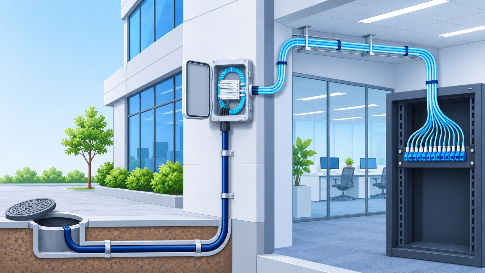
Every fiber route eventually hits a wall. Between the outside plant and the first patch panel inside the building sits a short section of route that contractors routinely under-specify and procurement teams routinely treat as an afterthought. That section — the building entry — is where the outdoor cable construction meets an indoor environment with different rules on water, fire, handling and termination. Get it right and the transition is invisible for twenty years. Get it wrong and you inherit water tracking along the cable into your splice trays, a failed fire inspection that delays handover, or a splice point buried in a wall cavity that nobody can reach when a fiber needs rerouting.
The building entry is not simply "where the cable ends." It is a distinct engineering and purchasing decision with its own bill of materials, its own installation sequence and its own acceptance criteria. How you handle it decides water ingress behavior at the wall, fire-code compliance inside the building, the cost and count of splices in the first fifty meters of the link, and how maintainable that link stays over its service life. The sections below walk through that decision the way we discuss it with contractors and ISPs before they place a lead-in cable order: why the transition deserves its own design step, what physically changes at the entry point, how the arrival method shapes the plan, and how to specify the outdoor cable and the entry hardware so the two sides meet cleanly.
Why the Outdoor-to-Indoor Transition Is a Decision of Its Own
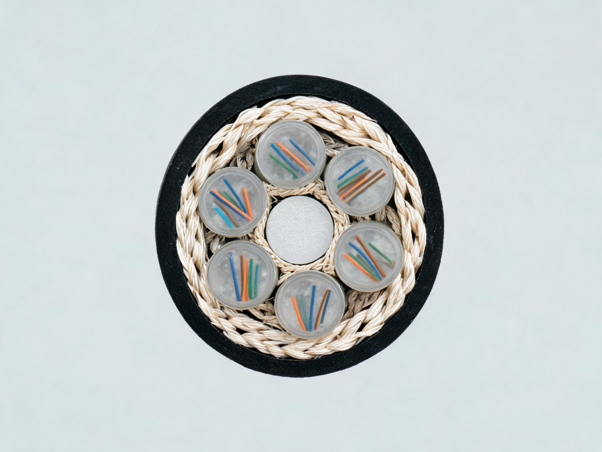
An outdoor single-mode cable is built to survive a hostile environment. A typical outdoor G.652D loose-tube cable uses gel-filled buffer tubes around a central steel wire or FRP strength member, protected by aramid yarn and a black polyethylene jacket. The gel inside the tubes blocks water migration along the fiber; the PE jacket resists moisture, abrasion and soil contact. That construction is exactly what you want in a trench, a duct or an aerial span — and exactly what you do not want to keep pulling into a riser closet, a horizontal ceiling space or a patch panel frame. Our outdoor G.652D single mode fiber optic cable page describes that construction in detail, and it is worth reading alongside this article when you plan the lead-in.
The indoor environment imposes requirements the outdoor cable was never designed to meet. Building and fire codes classify the cable pathways inside occupied structures — riser shafts, plenum air-handling spaces, horizontal runs through corridors — and require cables whose jackets and constructions carry the corresponding fire ratings. A PE-jacketed, gel-filled loose-tube cable carries no such rating. Terminating outdoor loose-tube fiber directly at an indoor patch frame is also awkward: the 250 µm fiber inside a gel-filled tube is fragile to strip and handle at a panel, and the gel itself migrates onto connectors and adapters if it is not cleaned meticulously. This is why purpose-built indoor tight-buffered fiber optic cable, with its 900 µm buffer on each fiber, exists in the first place — it strips cleanly, terminates directly at panels, and is available in riser and plenum constructions.
Given that mismatch, "keep pulling the same cable from the trench straight to the ODF" fails in two predictable ways, and both show up as expensive problems rather than as an immediate fault.
The first failure mode is water tracking. Water finds every path into a building along a cable — through the entry penetration itself, along the jacket surface, and in the case of poorly sealed or gel-degraded constructions, along the cable core. A cable that runs continuously from a wet duct or a buried splice point into an equipment room effectively becomes a wick. Water appears not at the wall, but at the far end: on the splice tray, in the closure you opened last month, or dripping onto the ODF. Because the damage point is meters or tens of meters away from where the water entered, the fault is hard to diagnose and even harder to permanently fix without reworking the entry itself.
The second failure mode is a fire-rating failure at inspection. The inspector walks the pathway and finds PE-jacketed outdoor cable inside the riser or the plenum space, or a jacket transition that happens behind a wall where nobody can verify it. The result is typically a punch-list item that blocks handover, and the correction — rerouting, replacing a section of cable, or retrofitting a compliant transition — costs far more than specifying the transition correctly during the original build. A properly planned entry point puts the outdoor-to-indoor changeover at a defined, accessible, code-compliant location, usually just inside the wall with the indoor cable starting at or immediately after the entry sleeve.
There is a third, quieter cost: splices. If the transition point is chosen carelessly — too far inside the building, or too close to the duct mouth — you end up splicing loose-tube fiber in cramped conditions, storing slack with nowhere to go, and paying for closures and splice labor that a well-placed entry splice point would have avoided. The transition decides the splice cost of the entire building feed, which is why it belongs in the purchasing conversation before the cable order is placed, not after.
What Changes at the Entry Point: A Side-by-Side View
The clearest way to see why the transition needs its own design step is to put the two sides of the wall next to each other. The table below summarizes the differences that matter when you plan a building entry.
| Dimension | Outdoor side (before the entry) | Indoor side (after the entry) |
|---|---|---|
| Cable construction | Loose-tube, gel-filled, central strength member, PE jacket; armored variants add steel tape or steel wire under the jacket | Tight-buffered 900 µm fibers under a common indoor jacket (LSZH or PVC), riser or plenum fire-rated |
| Water protection | Handles standing water, flooding and soil moisture; gel and jacket do the work | Assumes a dry environment; no water-blocking gel, so any water that arrives travels freely |
| Fire rating | Not rated for indoor pathways; PE jacket is the wrong material inside occupied spaces | Riser (OFNR) or plenum (OFNP) rating required by code, matched to the pathway |
| Termination | Loose-tube fiber is spliced, typically to pigtails, inside a closure or a dedicated splice point | Tight-buffered fiber can be spliced or directly terminated at panels; 900 µm buffer is panel-friendly |
| Bend radius handling | Larger radii; roughly 20x OD during install and 10x in service for a typical loose-tube build (typical values, confirm against the datasheet) | Smaller radii tolerated; roughly 10x OD static and 20x OD while pulling for typical tight-buffered builds (typical values, confirm against the datasheet) |
| Typical cable families | Outdoor G.652D loose tube, armored cable, ADSS or figure-8 self-supporting for aerial | Indoor tight-buffered distribution cable, LSZH variants where smoke toxicity matters |
Reading that table column by column explains the standard transition architecture. On the outdoor side you accept a larger, heavier, water-protected cable because the environment demands it. On the indoor side you need small, flexible, fire-rated, easy-to-terminate cable because the environment demands that instead. No single cable construction satisfies both columns — which is precisely why the entry point exists as a designed element rather than a place where a drum happens to run out.
The fire-rating row deserves a closer look, because it is where most inspection failures originate. If you are unsure which indoor construction your pathway requires, our guide on choosing indoor fiber optic cable for riser, plenum and horizontal runs walks through the pathway classifications and the cable constructions that satisfy each. The termination row also explains why the transition usually includes a splice: loose-tube outdoor fiber terminates cleanly only via splicing (typically to pigtails at a panel — see our article on specifying fiber optic pigtails for ODF, FTTH and data center networks), while the indoor tight-buffered fibers that continue into the building can be routed and terminated far more freely.
One more note on the materials row: where the indoor route passes through spaces with strict smoke and toxicity requirements, LSZH jacketing is often specified. Our article on what LSZH fiber optic cable is and when to specify it covers that decision, which belongs in the indoor-side bill of materials but is worth settling early because it affects the indoor cable order.
Mapping the Route to the Entry Point
Before you can place the entry hardware, you need to know how the outdoor cable arrives at the wall. Three arrival cases cover nearly every project, and each one changes where the transition point should sit and how much protection the last ten to twenty meters need.
Case 1: Ducted arrival
When the outdoor cable arrives in duct, the last duct section usually runs under a sidewalk or a road crossing into the building's cable vault or basement wall. The cable exits the duct at the vault, and this is where the transition generally belongs: the vault gives you a dry, accessible, inspectable space for the entry hardware, the drip loop, the splice point and the slack storage. Pull the outdoor cable from the manhole or handhole to the vault using normal duct-pulling practice — our contractor's guide to pulling fiber optic cable without exceeding tension and bend limits covers the tension and radius discipline that applies on this final pull, which is often the tightest bends in the whole route as the cable turns into the vault.
In the vault, complete the transition: outdoor cable enters, is spliced or connectorized to the indoor cable, and the indoor cable rises to the equipment room through an internal riser. Keeping the outdoor construction out of the occupied riser entirely is the cleanest way to satisfy the fire-rating requirement.
Case 2: Direct-buried arrival
When the route is direct-buried to the building, the last stretch of trench comes up to the foundation wall, and the entry sleeve penetrates that wall below grade or just above finished grade. Direct burial changes the calculus on the lead-in section: the cable is in soil contact right up to the wall, so the armored-versus-unarmored decision (covered in the next section) matters most here, and the trenching and backfill quality in the final meters matters more than anywhere else on the route. Our practical guide to installing direct-buried fiber optic cable covers trench depth, bedding, warning tape and backfill compaction — all of which apply to the final approach to the building, where careless backfill creates the water channeling that later finds your entry sleeve.
With a buried arrival, the transition point usually sits just inside the wall in a small entry cabinet or splice box, because there is no vault to work in. That makes the accessibility requirements in the next section even more important: whatever box receives the outdoor cable must remain reachable for the life of the link.
Case 3: Aerial arrival
When the feed comes in on poles, the cable transitions from the last span to the building — either dropping to a buried section at the base of the structure, or entering at an upper wall penetration. An aerial arrival adds a mechanical consideration the other cases do not have: the span and the drop introduce their own tension, sag and clamping questions, which our article on choosing and deploying figure-8 self-supporting fiber optic cable addresses for the span side, and our comparison of whether ADSS is the right choice for an aerial network covers the alternative where the full span is all-dielectric. If the aerial route is your arrival case, read those before locking the entry design, because the down-lead clamping and the drip loop geometry at the building face depend on the span construction.
Whichever case applies, the arrival method dictates one thing consistently: the outdoor cable should terminate its journey at a defined, protected, accessible transition point, and everything inside that point should be built for inspection and future work. The cross-section below shows the outdoor construction you are managing up to that point — the gel-filled tubes and strength member that make the outdoor side rugged, and the PE jacket that must not be allowed past the entry.
Designing the Entry Point: Sleeves, Sealing, and Drip Loops
With the arrival route mapped, the entry point itself comes down to four physical elements: the sleeve, the seal, the drip loop and the bend management. None of them are exotic, but each one is where entries fail in practice.
The entry sleeve
The cable should pass through the wall in a dedicated sleeve or short duct — never through a bare hole chased into the masonry. The sleeve serves several purposes at once: it protects the cable jacket from the sharp edges of the wall structure, it gives the sealant a defined cylindrical surface to seal against, it allows the cable to be replaced in the future without breaking the wall open again, and it creates a fire-stop location you can point to during inspection. Size the sleeve with headroom — a sleeve just barely larger than the cable OD makes sealing difficult and leaves no allowance for a future re-pull. For buried entries, the sleeve should slope slightly downward toward the outside, so that any water that does collect around it drains away from the building rather than into it.
The seal
An unsealed sleeve is a designed water channel. The annular gap between the cable jacket and the sleeve must be sealed from both the outside and the inside, using a mechanical seal or a rated sealant system appropriate for the sleeve material and the wall construction. Two things to verify on site: first, that the jacket surface the seal grips is clean and undamaged — a nicked or muddy jacket surface at the seal point is the most common cause of slow seepage; second, that the seal remains accessible. If the seal is buried behind fixed wall paneling or inside a sealed cabinet that requires demolition to open, the first re-entry will destroy it. Design the entry box or cabinet so the seal can be inspected and re-made with hand tools.
The seal does more than stop water. In many installations it also needs to limit gas ingress from the duct network into the building, and it forms part of the fire-stop at the penetration. Treat it as a rated component, not as a bead of silicone applied at the end of the day.
The drip loop
Water runs along a cable. That simple fact is the entire argument for the drip loop: before the cable enters the sleeve, it should dip below the entry point and rise back up, so that water running down the jacket drips off at the bottom of the loop instead of following the cable into the seal. On an above-grade entry, form the loop between the last fixing point and the sleeve; on a buried entry, form it inside the entry box immediately before the sleeve. The loop should be generous enough that the cable's minimum bend radius is respected at every point of the curve — for a typical loose-tube outdoor build, that means keeping the radius at roughly 10 to 20 times the cable OD depending on whether the cable is under tension at that moment (typical values, confirm against the datasheet supplied with the order). A drip loop kinked tight to save space is worse than no loop, because it combines a water trap with a bend violation.
Bend management at the wall face
The wall face is where cables get abused. The cable comes up out of a trench or out of a duct with mud on it, gets handled roughly during the final pull, and then has to turn ninety degrees into the sleeve. Check three things on site: that the last meter before the sleeve follows the minimum bend radius (not just visually — actually, along the whole curve); that the cable is fixed with a proper cable grip or clamp sized for the construction, not taped to a pipe; and that nothing in the final routing puts a permanent point load on the jacket where it crosses a wall edge. The datasheet for the cable you are installing states the manufacturer's own bend and tension limits — read those numbers against your entry drawing before the crew arrives, not after the cable is fixed in place.
Keeping the transition accessible
Finally, treat the entry as a service point, not a hidden joint. Whether the transition includes a splice or a connectorized transition, the slack storage, the closure or box, and the seal all need to be reachable in five years when a fiber count needs rerouting or a jacket section needs inspection. Our article on choosing a fiber optic splice closure and managing slack storage covers the closure and slack considerations that apply at the entry splice point; the short version for building entries is that the entry box should be large enough to open fully, re-splice and re-seal without disturbing the wall penetration itself.
Choosing the Outdoor Cable for the Lead-In Section
The last specification question is the outdoor cable itself. Two decisions dominate: whether the lead-in section should be armored, and how the core count and drum lengths for the building feed should be ordered.
Armored or standard PE on the lead-in?
Armor buys mechanical protection: steel tape or steel wire between the core and the outer PE jacket, which raises the cable's resistance to crush and to rodent attack. The typical numbers make the difference concrete — short-term tensile performance on the order of 3,000 N for steel tape armor versus 6,000 N for steel wire armor, and crush resistance on the order of 3,000 N/100 mm versus 4,000 N/100 mm respectively (all typical values, confirm against the datasheet supplied with the order). Against that, armor costs more per meter, is heavier to pull, and carries tighter bend behavior under load — a typical armored build expects roughly 15 times the cable OD once installed and roughly 20 times the OD while under pulling tension (typical values, confirm against the datasheet).
For lead-in sections, our working guidance is straightforward. Specify armored cable on the lead-in when the final approach is direct-buried in rocky or disturbed ground, when the last stretch passes anywhere rodents have access — basements, cable vaults, ceiling voids in older buildings — or when the route runs through areas with known rodent activity. Specify standard PE-jacketed loose tube when the cable arrives in duct under controlled conditions and the entry vault provides physical protection, since duct plus vault already does the mechanical job. For a fuller treatment of the armor decision, see our buyer's guide on when to use armored fiber optic cable, and the armored fiber optic cable product page for the construction details. Note two boundary conditions from that guide that matter at building entries: armored cable is not an aerial construction, and it is not intended to run into occupied indoor spaces as-is — both reinforce the same rule that the outdoor construction stops at the transition point.
Core count and the building feed
The core count you choose for the building feed determines the outdoor cable order, and it is worth getting right before quoting. Count not just today's lit fibers but the growth allowance and any future tenants or services on the same feed; our article on choosing the right fiber count for a fiber optic cable order gives a structured method. Once the count is fixed, the outdoor cable order follows: standard core counts typically carry a minimum order quantity of around 10 km, with custom builds from 20 km (typical, confirm with quotation), and standard configurations are typically dispatched within 15 to 20 working days after order confirmation (typical, confirm with quotation). If your project timeline has a hard handover date, read our article on MOQ and lead time when ordering fiber optic cable from a manufacturer before you commit dates to the customer, and confirm both figures against the quotation.
Drum lengths and the last partial drum
Outdoor cable is supplied on wooden drums in 2 km, 4 km and 6 km standard lengths. Most building feeds do not consume a full drum: the lead-in from the splice point or the vault to the building might be 50 to 200 meters, which means the building feed is usually fed from a partial drum length or from a purpose-cut length. Plan this deliberately. If the building feed is being cut from a drum that also serves the upstream route, decide in advance where the drum terminates — the transition point at the building is a natural termination, and cutting the drum there avoids a mid-route joint you would otherwise have to justify. If the feed is a dedicated short length, order it as its own configuration so the lead-in arrives as a single continuous piece with no mid-span splice between the entry and the first splice point.
One practical check at delivery: confirm the drum markings and lengths against the order before the drum leaves the yard, since the entry design assumed the cable would arrive as a continuous run. Our article on how fiber optic cable is packed and shipped for export covers the reel markings, packing options and delivery inspection points that apply to any drum-based order, including the partial-length configurations common for building feeds.
Finally, remember that all fiber optic cables from Nexora carry a warranty of 12 months from shipment date — a window that starts well before the entry is installed, which is one more reason to confirm the sample and the datasheet details before the bulk order. Our guide on validating a fiber optic cable sample before placing a bulk order walks through that verification step, and the datasheet you receive with the order remains the authority for every numeric parameter discussed above.
Three Ways to Structure the Transition (and When Each Fits)
Once the outdoor cable has arrived at the building and been properly sealed into the entry, someone still has to decide where the outdoor-to-indoor handoff physically happens. There are three workable structures, and the choice between them is driven by maintenance access, fire code path, splice cost, and how likely the network is to be reconfigured later. None of the three is universally correct; each fits a different building and a different operational model.
Option A: Splice at the entry box, just inside the wall. The outdoor loose-tube cable terminates in a sealed entry box mounted immediately inside the building entry. Inside that box, each outdoor fiber is fusion-spliced onto indoor tight-buffered cable, which then runs riser or horizontal routes to the distribution points. The splice sits as close to the wall as possible.
Option B: Bring the outdoor cable deeper and splice at the first rack or ODF. The outdoor cable continues past the entry along a protected route — a cable tray, a dedicated shaft, a conduit run — until it reaches the first equipment room. There it is spliced directly onto pigtails or a termination cassette at the ODF or rack, and the indoor distribution cable runs from that rack outward. This structure requires that the indoor portion of the route be legally and physically suitable for outdoor-jacketed cable — typically conduit or tray through non-occupied service space.
Option C: Long outdoor/transition run direct to the rack. In smaller sites — a street cabinet feeding a small office, a base station shelter, a compact POP — the outdoor cable is routed all the way to the rack with no indoor cable at all, and splices land on pigtails inside a small rack-mount closure or box. This is common where the "indoor run" is short and stays entirely within service space, not occupied space.
| Option | Where the splice sits | Pros | Cons | Typical use |
|---|---|---|---|---|
| A — Entry box splice | Sealed box just inside the wall | Outdoor jacket never enters the building; fire-rated indoor cable covers all occupied routes; easy to inspect the seal | Extra splice loss and splice cost per fiber; entry box needs enough space for fusion work; two cable orders to match | Multi-floor buildings, MDUs, campuses where indoor routes pass through risers and plenum zones |
| B — Splice at first rack/ODF | ODF or rack in the first equipment room | Fewer intermediate splices; termination and splicing happen where technicians work daily; simple documentation | Outdoor cable traverses building interior — route must be conduit/tray through service space; fire code acceptance must be confirmed; harder to retrofit | Industrial buildings, basements, POPs where the equipment room is close to the entry |
| C — Direct outdoor run to rack | Rack-mount closure or box at the rack | Simplest bill of materials; single cable type; lowest total splicing when the route is short | Only defensible where the entire indoor path avoids occupied space; sealing at the rack becomes critical; no indoor redundancy | Small shelters, street-to-cabinet feeds, single-room sites |
How do you choose? Start with the fire code path: if the indoor route passes through a return-air plenum or a riser serving multiple floors, Option A is almost forced, because the cable past the entry must carry the correct fire rating. Next, weigh maintenance access. A splice buried in a cramped entry closet is cheap to build and expensive to service; a splice at a staffed ODF is the reverse. Splice cost scales with fiber count — at 2–12 cores the extra splice row of Option A is trivial; at 144 cores it is a real line item, and Option B starts looking attractive. Finally, think about future splits. If you expect additional indoor distribution legs later, an entry-box splice with generous slack storage gives you a clean point from which to grow; if the network is fixed, Option C removes a layer of hardware entirely.
Whichever structure you pick, the fiber inside must match: the outdoor feed is typically G.652D single mode, so the indoor cable should be OS2 single mode unless you have a deliberate reason otherwise — a mismatch we return to in the mistakes section.
Fire-Rating and Jacket Compliance on the Indoor Side
The jacket rating of the indoor cable is not a property you choose once for the whole building. It is dictated, zone by zone, by the spaces the indoor run passes through. A run that climbs a riser shaft between floors typically requires a riser-rated cable (OFNR). A run that passes through a plenum — the return-air space above a ceiling or under a raised floor that also moves air — typically requires plenum-rated cable (OFNP), which uses jacket materials with lower flame spread and smoke production. Where smoke toxicity is the driver rather than air handling — enclosed public corridors, tunnels, transport infrastructure — LSZH (low smoke zero halogen) jacketing is commonly specified; you can read the full reasoning in our article on when to specify LSZH fiber optic cable.
The classic buyer mistake is ordering a single jacket type for the whole building — usually the cheapest one — and then discovering at inspection that the plenum section fails. The fix costs either a re-pull or a mid-route splice into correctly rated cable, both more expensive than ordering the route correctly the first time. Walk the route before you order: list every zone it crosses, note which zone is the most demanding, and either buy cable rated for the most demanding zone for the entire run, or plan the jacket transitions deliberately at accessible splice points.
Indoor tight-buffered cable is available in OS2 single mode and OM3/OM4 multimode, 2–144 cores, with LSZH or PVC jackets and riser or plenum fire ratings; typical bend radius is 10x the cable diameter static and 20x during installation, and typical lead time is 15–25 working days (typical values, confirm against the datasheet supplied with the order). The 900 µm tight buffer on each fiber is what makes this cable type the natural splice partner for outdoor loose-tube fiber: it strips cleanly and terminates directly at patch panels without fan-out kits. Our guide to choosing indoor cable for riser, plenum, and horizontal runs walks through the rating selection zone by zone.
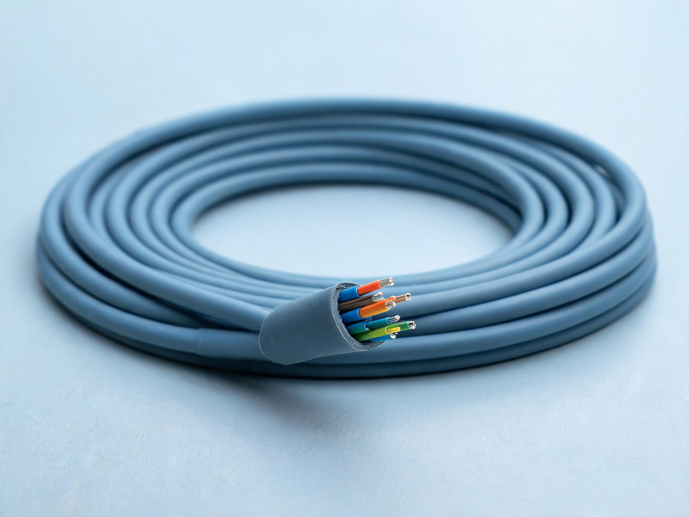
The color-coded 900 µm buffers visible on the stripped end above are the same color sequence used throughout the industry, which matters when you are matching outdoor loose-tube fibers to indoor tight-buffered fibers across a splice tray — the fiber color code is your roadmap.
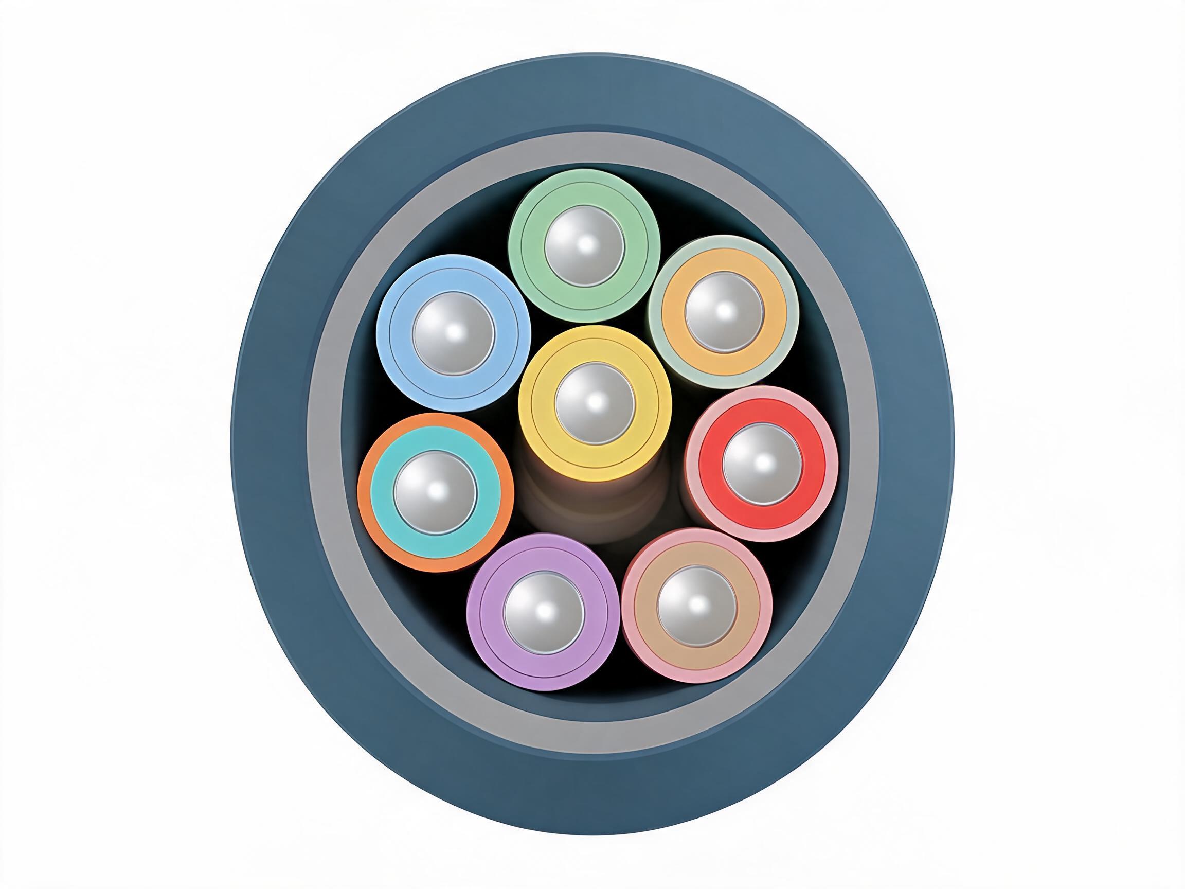
Comparing the cross-section above with the outdoor loose-tube construction earlier in this article makes the engineering logic of the transition visible: the outdoor cable protects fiber in gel-filled loose tubes against water and temperature; the indoor cable trades that protection for flexibility, strip-ability, and fire performance. The splice at the entry is exactly where one protection regime hands over to the other.
Slack, Splice Closures, and Storage at the Entry
Slack is the cheapest insurance in fiber construction, and the building entry is one of the two places (the other being aerial splice points) where omitting it is most often regretted. The reasons are concrete. First, re-splices: a fusion splice consumes a short length of fiber each time it is remade — typically several tens of centimeters per rework — and entry splices are exactly the ones that get remade, whether because of a damaged pigtail, a reorganization of the entry, or a fault on the outdoor side that forces the closure to be opened and the splice re-terminated. Second, building refits: walls move, doors relocate, ceilings come down, and a cable with no slack at the entry is a cable that must be re-pulled from the nearest splice point when anything changes. Third, testing: OTDR acceptance testing and future troubleshooting both benefit from accessible fiber at the entry.
There is no single mandated slack figure, and any number is a project decision, but common practice is to leave enough coiled fiber on each side of the splice to allow multiple re-splices plus modest relocation — engineers commonly plan this in the range of a few meters per side, sized to the closure's storage capacity. What matters is that the slack is coiled, secured, and protected, not left as a loose loop on the floor. Our article on splice closure selection and slack storage covers the storage geometry in detail — minimum bend diameter in the tray, tie-down practice, and labeling.
The entry box or closure you choose must be both sealed and re-openable. A sealed, gasketed entry box keeps dust, moisture, and vermin out of the transition point; a re-openable design means that seal can be broken and restored without cutting the cable. Check three things when selecting one: capacity (does it hold the splice trays and slack coils for your fiber count, with room for growth?), sealing (gasket quality and gland compatibility with the actual cable outer diameter — an oversized gland is a failed seal), and mounting (can a technician open it with tools and light in the space where it will actually live?).
On the rack side of the transition, the splice usually lands on pigtails rather than bare splices onto patch cord. A pigtail — a short fiber with a factory-attached connector — is fusion-spliced onto the incoming fiber, giving you a factory-quality connector at the panel without subjecting a connector to the pull. Our article on specifying pigtails for ODF, FTTH, and data center networks covers connector types and how to match them to your panel, and the ODF planning guide handles the rack-side layout, labeling, and port allocation.
Grounding, Bonding, and Metallic Members
The transition point is also where the metallic content of the outdoor cable gets addressed. Outdoor cables commonly carry metal: a steel tape or steel wire armor layer in armored builds, a steel wire central strength member in many loose-tube designs, and occasionally metal armoring or strength elements in aerial constructions. Indoor tight-buffered cable, by contrast, is typically all-dielectric. That means the building entry is the natural — and usually the required — place where the metallic path of the outdoor cable ends.
Why does this matter practically? A long metallic element that extends into the building can transfer lightning-induced surge potentials, earth potential differences, and accidentally impressed voltages from outside toward equipment and people inside. The standard approach, governed by local electrical and telecom codes, is to terminate, bond, and ground the metallic members at the entry, per the practices your local code and the project specification require — we will not invent specific clause numbers here, because the governing documents differ by jurisdiction and the AHJ (authority having jurisdiction) has the final word. What you can control as a buyer and installer:
- Know what metal your cable actually contains. Steel tape armor, steel wire armor, and steel central members are all conductive; FRP (fiberglass reinforced plastic) central strength members are not. This is on the datasheet — check it before the cable arrives, not after.
- Plan the bonding point at the same location as the splice/entry box, so the metallic path ends where the outdoor construction ends.
- Ensure the bonding conductor, ground bar, and route to the building's grounding system are in the scope of whoever installs the entry — this is a common "nobody quoted it" item.
- If your route genuinely does not need armor or a steel member (duct installation in a low-rodent, low-dig area), specifying an FRP central member build removes most of the problem at the source.
That last point deserves emphasis for procurement: a non-metallic build simplifies the entire entry design — no bond point, no ground conductor, one less inspection item. It costs slightly more per kilometer than a steel-member build in many cases, but on a project with a dozen building entries, the saved grounding work at each one can offset it. Our datasheet-reading guide shows exactly where the strength member material and armor construction appear on the document.
A Pre-Order Checklist for the Building Entry Package
The building entry fails most often not because any single component is wrong, but because the components were ordered independently and never reconciled. The outdoor cable order, the indoor cable order, and the entry hardware order each look fine in isolation and don't fit together on site. Use this checklist to reconcile them before you commit.
| Item | What to confirm |
|---|---|
| Arrival method | How the outdoor cable reaches the entry: direct burial, duct, or aerial — determines jacket, armor, and whether a transition to non-armored construction is needed at all |
| Entry position | Exact wall penetration point, its height, and the space available inside for the entry box, splice trays, and slack coils |
| Indoor route length | Measured route from entry to each termination point, including vertical rises and service loops — this sets the indoor cable drum lengths |
| Fire-rating zone | Every zone the indoor run crosses: riser, plenum, LSZH-required corridors; the most demanding zone governs the order (or the planned jacket transitions) |
| Splice point location | Option A, B, or C from earlier — where exactly the outdoor-to-indoor splice happens and what hardware that implies |
| Fiber counts both sides | Outdoor cable cores vs indoor cable cores — they must match at the splice, with room for future growth if planned |
| Fiber type match | OS2 single mode indoor cable against a G.652D outdoor feed — not OM3/OM4 multimode unless the design genuinely calls for mode conversion |
| Slack lengths | Slack planned per side of the splice, and where it is stored; slack requested at the drum level (extra length per section) or coiled at the entry |
| Closure type | Entry box/closure capacity, sealing (gland sizes matched to actual cable ODs), re-openability, and mounting space |
| Grounding needs | Whether the outdoor build contains steel armor or steel member; if so, bonding hardware and conductor route at the entry, per local code |
| Datasheet confirmation | All the above verified against the datasheets supplied with the order — attenuation, bend radius, temperature range, and construction are typical values, confirm against the datasheet supplied with the order |
Walk the list in order and it mirrors the physical build. Arrival method and entry position fix the geometry. Route length and fire zones fix the indoor cable order. Splice point and fiber counts fix how the two orders meet. Slack, closure, and grounding fix the entry hardware. The final row — datasheet confirmation — is the discipline that catches the mismatches: two cables with different core counts ordered by two people, an entry box whose glands don't fit the armored cable's outer diameter, an indoor drum length cut to the drawing rather than the measured route. Fifteen minutes with the datasheets against this table is cheaper than any of those outcomes.
Mistakes That Cost the Most at the Building Entry
These are the recurring, expensive errors we see contractors and procurement teams make at transitions — each one is avoidable at specification time.
1. Running armored cable into occupied space as-is. Armored outdoor cable is not an indoor product. Its steel armor and PE jacket do not carry an indoor fire rating, and most local codes prohibit or restrict that construction in occupied areas and air-handling spaces. The fix — re-terminating or splicing after the fact — costs far more than planning the transition correctly. Our buyer's guide on when to use armored fiber optic cable draws the line explicitly.
2. One jacket rating for all zones. Covered earlier, but it earns its place on this list: ordering OFNR cable and discovering a plenum segment mid-route is one of the most common inspection failures in indoor fiber work. Walk the route; order per zone.
3. Sealing forgotten. The wall penetration is a hole in the building envelope. Leaving it unsealed — or sealing it around the cable without a proper sleeve and firestop — invites water ingress, pests, and a failed fire inspection. The entry sleeve and firestop belong in the BOQ from day one, not as a site improvisation.
4. Slack omitted. A splice with zero slack works perfectly on commissioning day. The first re-splice, refit, or relocation turns it into a re-pull. Leave planned slack on both sides, stored properly.
5. Splice at the wrong height or access. An entry box mounted two meters up a wall behind a pipe rack, or inside a ceiling plenum with no access panel, will be serviced badly or not at all. Mount splice points at working height in accessible space, and confirm that access during the site survey, not after installation.
6. Wrong fiber type on the indoor side. Ordering OM3/OM4 multimode indoor cable against a G.652D single mode outdoor feed is a mismatch that only becomes obvious at the splice — the fibers will not couple, and no amount of splicing skill fixes it. If the outdoor feed is single mode (as most transport and FTTH feeds are), the indoor cable is OS2. If you genuinely need multimode inside, that is a media-conversion design decision made in the design phase, not a cable substitution made at the warehouse. Our fiber count and selection guide helps you pin down both count and type before ordering.
Specifying the Transition Package from Your Supplier
Everything above collapses into a single discipline: order the outdoor and indoor cables as one coherent package, not two separate transactions. When you brief your supplier, the following information lets the factory match the two builds and cut the drums to lengths that actually fit the site:
- Arrival method and route: direct burial, duct, or aerial to the entry; the entry construction; and whether the outdoor cable needs armor or an FRP (non-metallic) central member based on the route and your grounding plan.
- Indoor route description: total lengths per leg, which zones (riser/plenum/LSZH) each leg crosses, and where jacket transitions occur if any.
- Core counts both sides: outdoor cable cores and indoor cable cores, matched at the splice point, with any spare-fiber allocation stated explicitly.
- Fiber type: G.652D single mode outdoor with OS2 indoor, unless the design specifies otherwise.
- Drum lengths: outdoor sections cut to the measured route plus slack; indoor sections cut to the measured indoor route. Standard outdoor configurations ship on wooden drums in 2 km, 4 km, and 6 km lengths, so plan splice points with those lengths in mind to avoid unnecessary mid-route joints.
- Splice plan: Option A, B, or C, and where each closure sits — so the factory knows if you need fan-out-ready constructions or specific slack allocations.
On commercial terms, be realistic about what standard means. For standard outdoor core counts, MOQ is typically 10 km, with custom builds from 20 km; standard configurations are typically dispatched within 15-20 working days after order confirmation (typical values, confirm with your quotation). Armored builds carry a reference MOQ of 2,000 m per configuration with lead times of 10-25 working days depending on configuration; indoor tight-buffered cable typically ships in 15-25 working days (all typical values — confirm against the quotation). Our article on MOQ and lead time when ordering from a manufacturer explains how these numbers are set and how custom builds change them.
Before committing to volume, validate the transition physically. Order samples of both cables, splice them in the entry-box configuration you plan to use, and confirm that the tight buffer strips cleanly against the outdoor fiber, that the closure glands seal on both outer diameters, and that your crew's termination workflow is sound. Our guide on validating a cable sample before a bulk order gives the test sequence. When the shipment arrives, check it before your crews mobilize — the packing and delivery inspection guide covers drum condition, labeling, and length verification. And because every parameter in this article is a typical value, confirm against the datasheet supplied with the order — our datasheet-reading guide tells you which lines matter most for an entry transition: strength member material, armor construction, jacket rating, and outer diameter. All fiber optic cables from Nexora are covered by a warranty of 12 months from shipment date.
Frequently Asked Questions
Can I run outdoor cable all the way to the rack?
Sometimes — this is Option C from earlier in the article. It is defensible when the entire indoor path stays within service space (conduit, tray, dedicated shaft) and never crosses occupied areas or air-handling plenums where an outdoor PE jacket is not permitted. If any part of the route passes through occupied space, the code-compliant answer is to splice to a rated indoor cable at or near the entry. Confirm the route against your local code before committing, and check that the rack-side entry point is properly sealed and, if the outdoor build is metallic, bonded.
Where exactly should the splice box be mounted?
Inside the building, immediately after the wall penetration, at a height and location a technician can work at with tools and light — typically 0.5 to 1.5 m above floor level in a clean, dry, accessible position. Avoid ceilings without access panels, spaces behind fixed equipment, and any location where water could collect. The box must be reachable for future re-splices, which is the whole point of leaving slack. Mount it on a suitable backboard with the slack coils secured, and keep the wall sleeve and firestop on the outside of the same wall section.
How much slack should I leave at the entry?
There is no universal mandated figure — it is a project decision, but common practice is enough fiber on each side of the splice to allow several re-splices plus modest relocation, often planned in the range of a few meters per side, sized to the closure's storage capacity. What matters more than the exact number is that the slack is specified before the order (so drum lengths account for it), coiled and secured in the closure rather than left loose, and documented on the as-built drawing so the next technician knows it exists.
Does the outdoor cable need to be grounded?
If the cable contains metallic elements — steel tape armor, steel wire armor, or a steel central strength member — then yes, the metallic path should be terminated and bonded at the building entry in accordance with your local electrical and telecom codes and the project specification. If the cable is built with an FRP (non-metallic) central strength member and no armor, there is no conductive path to bond, which is why non-metallic builds simplify the entry design. Local codes govern the specifics of the bonding hardware and the ground bar connection; verify with the AHJ before installation.
Can one cable be both outdoor-rated and indoor-rated?
Cables marketed as indoor/outdoor or transition cables exist, typically with a ruggedized jacket that passes limited indoor fire ratings. They can suit short, simple transitions — a cabinet-to-rack run through a single service space, for example. What they generally do not do is combine full outdoor environmental performance (gel-filled loose-tube water blocking, wide temperature range, high tensile) with plenum-level fire performance in one jacket at a sensible cost. For multi-zone indoor routes, the standard answer remains: outdoor cable to the entry, splice to correctly rated indoor cable, per the fire zone. Check any indoor/outdoor product's datasheet for exactly which ratings it actually carries — do not assume the marketing name is the rating.