
A step-by-step buyer's guide to validating fiber optic cable samples before placing a bulk order: what a complete sample pack should include, document review, arrival inspection, optical tests, connector and pigtail checks, pilot runs, red flags, and how to freeze validated results into purchase order terms.
Why Sample Validation Decides Your Bulk Order Risk
For telecom contractors, ISPs and distributors, the moment a bulk fiber optic cable order leaves the factory, most of the risk has already been locked in. If the attenuation runs high, the jacket cracks in cold weather, or the connector polish is inconsistent, you discover those problems after the containers have shipped, cleared customs and arrived at your warehouse. At that point your options are narrow: negotiate a claim across borders, sort rework crews on site, or absorb delays that ripple through your project schedule. Sample validation exists precisely to move that discovery earlier, to the point where correcting a problem costs the supplier a new sample run instead of costing you a project milestone.
The economics are simple. A sample pack costs a fraction of a bulk order and can be evaluated in days with basic tools — a visual inspection bench, a light source and power meter, and in many cases an OTDR borrowed from an installation team. Skipping or rushing this stage does not save meaningful time; it only shifts the cost of supplier selection from a cheap, controlled exercise to an expensive, public one. Buyers who treat sample approval as a formality, accepting whatever arrives in the box without checking it against their order requirements, are effectively testing their cables on the customer's network instead of in their own workshop.
Sample validation also disciplines the conversation with the supplier. When you evaluate a sample against written criteria, you produce documented evidence of what the factory can deliver. That evidence later becomes the basis for contract terms: the attenuation values you measured become the acceptance values in your purchase agreement, the jacket marking you checked becomes the marking specification, and the test report you received becomes the format you expect with every production lot. A sample evaluated casually gives you none of this. A sample evaluated properly gives you leverage and clarity for the entire commercial relationship.
There is a further dimension that buyers sometimes overlook: the sample round is your first real test of how a manufacturer communicates. How quickly the sample pack arrives, whether the documents match the cables in the box, whether the factory discloses test conditions and limitations honestly — these behaviors during sampling reliably predict how the supplier will behave when a production problem appears. A manufacturer such as Nexora, which verifies cable and patch cord quality before shipment in its own QC process, will typically welcome structured sample evaluation; a supplier who resists your checklist is telling you something worth hearing before you commit volume.
What a Complete Sample Pack Should Include
Before you evaluate anything, you need the right things to evaluate. A surprisingly common failure mode in sample rounds is an incomplete pack: cable arrives but no datasheet, patch cords arrive but no factory test report, or everything arrives but the reel labels carry no traceable batch information. An incomplete pack is not just inconvenient — it means you cannot verify that the sample corresponds to what would actually be produced for your order, which undermines the whole exercise. When you request samples, specify the pack contents in writing, and treat a pack that arrives missing items as data about the supplier, not as a shipping oversight to be waved through.
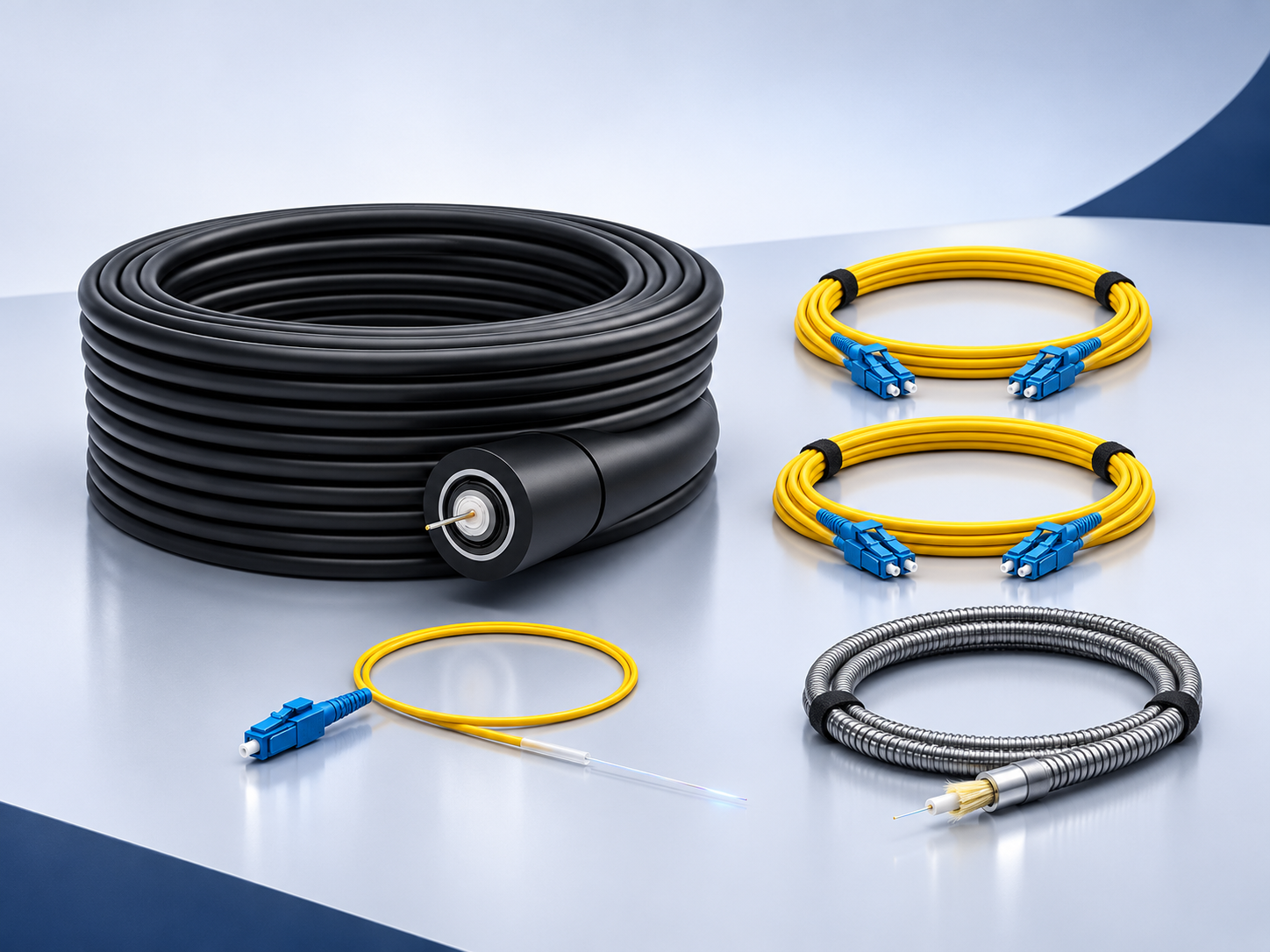
At minimum, a pack for a cable project should include a length of the actual outdoor cable you intend to order — for example, a loose-tube G.652D single mode cable with water-blocking elements and a PE jacket, or its armored variant with steel tape or steel wire armor if direct burial and rodent protection are part of your scope. The sample should be long enough to allow OTDR measurement and a mid-span splice trial, not a token half-meter offcut. Alongside the cable, include connectorized samples that represent the terminations you will deploy: patch cords in the relevant connector families — SC-SC, LC-LC duplex, FC-FC — and pigtails with one connector and a bare fiber end for fusion splicing, in the polish type (UPC or APC) your network design calls for.
The documents matter as much as the physical items. The pack should contain the product datasheet, a factory test report generated for the actual samples shipped (not a generic template), copies of relevant certifications, and the reel label information that identifies the production batch. If packing matters to you — and for export orders it always does — request the packing specification as well, so you can see how reels will be protected and labeled in transit. A manufacturer's OEM/ODM capability is also easier to judge from a complete pack: you can see whether custom jacket printing, custom lengths and custom labeling are rendered consistently on real product rather than promised in a brochure.
Use the checklist below when specifying and receiving your sample pack. Every row is something you can verify on arrival, and each one feeds a specific stage of the evaluation described later in this article.
| Sample Pack Component | What to Check | Why It Matters |
|---|---|---|
| Cable sample (e.g., loose-tube G.652D outdoor cable, or armored variant) | Sufficient length for optical testing and a splice trial; construction matches the datasheet; jacket marking legible and correct | The physical sample is the basis for every measurement; too-short samples cannot be tested realistically |
| Connectorized samples (patch cords and pigtails) | Correct connector types and polish (SC/LC/FC, UPC/APC); boot and body quality; custom lengths as requested | Termination quality drives link loss; patch cords and pigtails often fail differently than the cable itself |
| Product datasheet | Fiber type, attenuation values, cable construction, jacket material, connector performance specifications | The datasheet is the reference against which every measurement and document is cross-checked |
| Factory test report for the actual samples | Reported values correspond to the shipped samples; test conditions stated; format suitable for production lots | Shows what the factory's own QC can document, which you will rely on for every future shipment |
| Reel label information | Batch or lot number, length, fiber type, production date; matches the test report | Traceability links your evaluation to a production batch and anchors any future claim |
| Certification copies (e.g., ISO management-system certificates) | Certificate numbers, validity dates, issuing body | Evidence of systematic quality management behind the products you are sampling |
| Packing specification | Reel type, protection, palletization, labeling for export shipment | Packing failures damage good cable; better to review the scheme before bulk volume ships |
Note on certificates: always verify that a certificate's scope actually covers the products you are buying — a management-system certificate applies to the factory's processes, not to product performance, so check both what the certificate covers and what separate product-level evidence exists.
Review the Documents Before You Touch the Cable
It is tempting to unbox the cable first and read the paperwork later, but the correct order is the reverse. The documents define what the physical sample is supposed to be; if the paper and the product disagree, you want to know that before investing workshop time in measurements. Document review also takes no special equipment, so it is the fastest way to eliminate a mismatched or carelessly prepared sample pack.
Start with a systematic cross-check of the datasheet against your order requirements. Every parameter you specified in your RFQ — fiber type, attenuation coefficient at the relevant wavelengths, tube count, jacket material and thickness, armor type, temperature range, connector performance — should appear on the datasheet at a value that meets or exceeds your requirement. Where a value is stated as typical rather than maximum, note that distinction: typical insertion loss figures such as 0.3 dB on a patch cord are representative values, and your acceptance criteria should reference the guaranteed maximums, subject to the datasheet. If you need a refresher on how datasheet parameters map to real buying decisions, the guide on how to read a fiber optic cable datasheet before you buy walks through the key fields in detail.
Next, examine the factory test report. The critical question is whether it documents the actual samples in your box or is a generic document with no serial or batch linkage. Check that the reported values — attenuation, sample length, jacket marking verification — are plausible and internally consistent: a report claiming better-than-theoretical attenuation on a long sample deserves skepticism, and a report whose length does not match the reel label is a red flag in itself. Pay attention to stated test conditions and equipment, because the report's credibility determines how much weight you can put on it when converting sample results into contract acceptance values. A manufacturer that publishes how it verifies cable and patch cord quality before shipment, as Nexora does, should have no difficulty producing a report that withstands this scrutiny.
Then verify the reel label. At minimum it should carry the batch or lot number, cable length, fiber identification and production date, and those fields should agree with the test report and the datasheet. The label is your thread of traceability: when bulk reels arrive months later, matching label formats and batch numbering tells you the same production system stands behind the shipment. Inconsistent, handwritten or missing labels during the sample round are cheap to discover and expensive to ignore.
Finally, review the certification copies against what your market and your customers actually require. Confirm validity dates, confirm the issuing body is credible, and — as noted earlier — confirm that the certificate scope covers the relevant products or processes rather than an adjacent activity. If your project or your customers demand specific product-level certifications, the sample round is the right time to obtain them, not after the bulk order. A structured approach to which certificates to demand before ordering, and how to verify them, is covered in the article on what certifications you should require from a fiber optic cable manufacturer.
Only when the documents hang together — datasheet, test report, reel label and certificates all consistent — should you move the sample to the bench. Everything you measure afterwards is then measured against a verified reference, which is what makes the results usable in the contract negotiation described later in this article.
Visual and Mechanical Inspection on Arrival
With the paperwork reviewed, the next step is to put your hands on the cable itself. Documents can describe a product accurately or inaccurately; the physical sample settles the question. Before any optical testing, spend time on a careful visual and mechanical inspection, because many of the most expensive field problems — crushed buffers, missing water-blocking, illegible jacket printing — are visible long before a light source is ever switched on.
Start with the jacket and the print legend. Run the full sample length through your hands and check for scratches, dents, bubbling, or uneven extrusion. Then read the printing: it should be continuous, legible, and consistent in spacing, and it should carry the information you agreed on — manufacturer name, cable type, fiber count, standards references, and year of manufacture. Meter marks deserve particular attention. If the printed length disagrees with the measured length later in your optical checks, you have an immediate quality signal. Faint, smudged, or drifting print legends are a common complaint from buyers who accepted samples without checking them at delivery.
Next, cut a short cross-section from one end — a few centimeters is enough — and compare the internal construction against the datasheet, item by item. Count the loose tubes and fibers per tube. Confirm the strength members are what the datasheet claims, whether aramid yarn, glass rope, or steel. For an armored design, verify that the armor is actually present and of the type specified: corrugated steel tape versus steel wire changes both crush performance and installation behavior. Check that water-blocking compound is visibly present in the tube and in the cable core, not just claimed on paper. For an outdoor PE-jacketed armored cable intended for direct burial and rodent protection, this cross-section check is the single fastest way to confirm you received the design you ordered rather than a lighter variant.
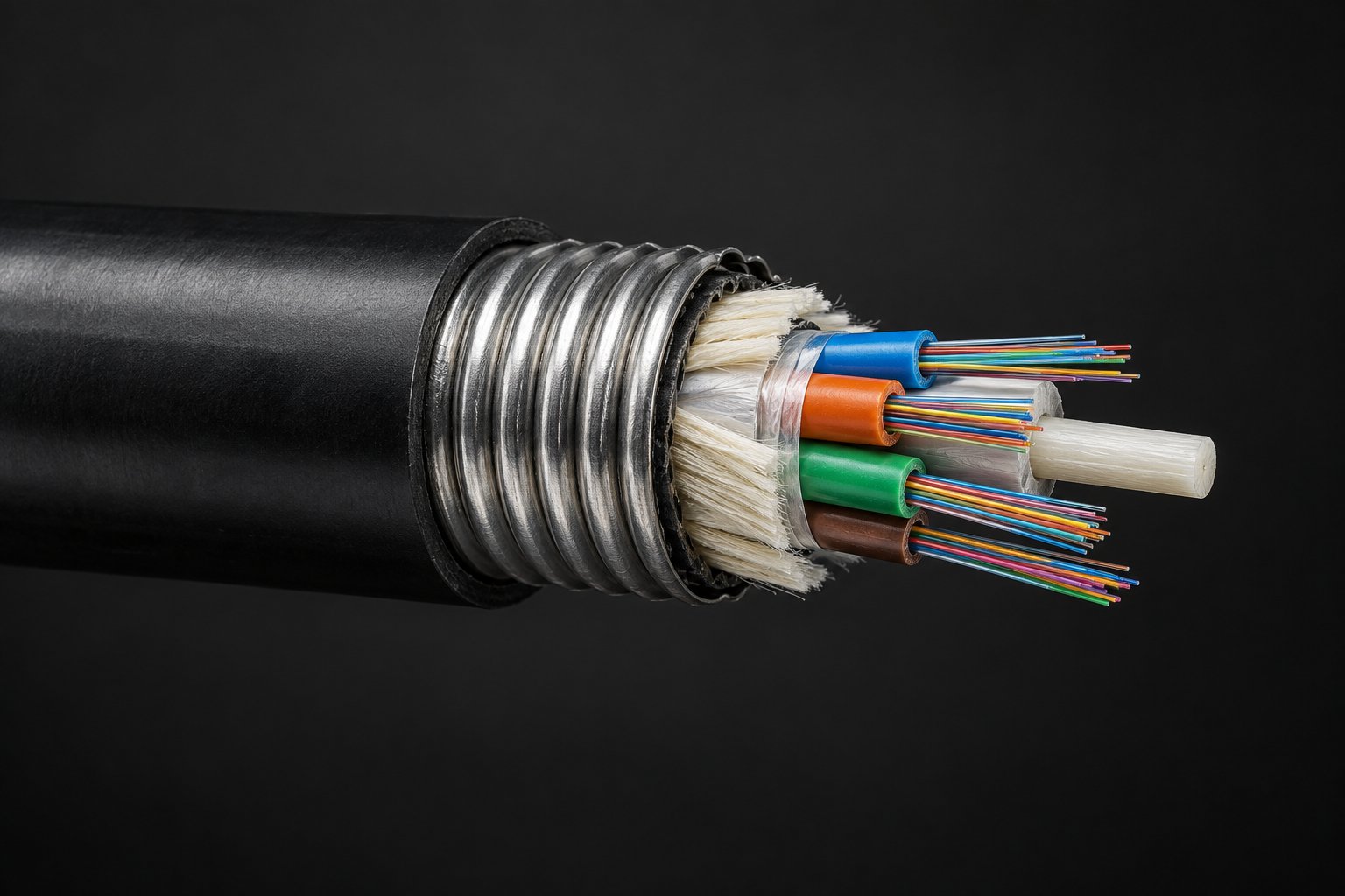
While the cable is opened up, also check fiber and buffer color coding. The fibers inside each loose tube should follow the recognized color sequence, and the tubes themselves should be identified consistently. If your crews work to a color-code convention — and most do — confirming the sample matches it now avoids splicing errors months later. Our guide on the fiber optic cable color code and how to use it on site covers the standard sequence and how crews apply it during installation.
Finish the mechanical inspection with a few simple handling checks. Bend the cable around a radius roughly matching your planned installation practice and look for jacket kinking or whitening. Strip one tube end and one fiber end using your normal tools to confirm the buffer diameter and coating strip force feel normal to an experienced technician. Weigh and measure the drum, and record the reel condition — a warped or damaged reel on the sample tells you something about how bulk reels will survive transit. None of these checks requires laboratory equipment, yet together they catch a large share of sample-related problems.
Optical Tests You Can Run on a Sample
Once the sample passes visual inspection, move to optical verification. The good news for buyers without a laboratory: the most meaningful checks can be done with a light source and power meter, a basic OTDR, a fiber microscope, and a reliable tape measure or length counter. What matters is not owning exotic instruments but running a disciplined set of measurements and recording the results against the datasheet, so the numbers become the baseline for the bulk order.
For connectorized samples such as patch cords and pigtails, insertion loss measured with a light source and power meter is the primary acceptance figure. Measure at 1310 nm for single mode samples, record the value for every fiber, and compare against the datasheet's maximum insertion loss rather than its typical value. Our article on how to test a fiber optic link with a light source and power meter walks through the reference-setting and measurement procedure step by step, and the same method applies directly to sample validation.
An OTDR trace on the sample adds a different kind of evidence. It shows attenuation along the length, confirms there are no discrete events such as breaks or kinks hidden along the span, and verifies the fiber length against the reel label. For bare cable samples, launch the test from both ends if the sample is long enough, and keep the traces — they become reference documents for the bulk shipment. Our guide on using an OTDR to accept a new fiber optic cable installation explains the trace features worth reading, and the same reading applies at sample stage.
The table below summarizes an acceptance-style test set that a buyer can realistically run with basic instruments. Treat the numeric thresholds as typical industry values, subject to datasheet — the datasheet for your specific product is always the governing document.
| Check | Typical Method | What Good Looks Like |
|---|---|---|
| Insertion loss (connectorized samples) | Light source and power meter at 1310 nm (single mode) or 850/1300 nm (multimode), reference set before measurement, every fiber recorded | Each fiber within the datasheet maximum insertion loss — typically 0.3 dB or better for single mode connectors, subject to datasheet; results consistent across all fibers, with no outlier |
| OTDR trace on the sample span | OTDR test from one or both ends at 1310 and 1550 nm, appropriate pulse width for the sample length, traces saved as PDF or SOR files | Smooth, event-free trace; attenuation typically around 0.36 dB/km or better at 1310 nm and around 0.22 dB/km or better at 1550 nm for G.652D fiber, subject to datasheet; no reflective or non-reflective events along the span |
| Connector end-face inspection | 400x fiber microscope on every connector, checked against the relevant IEC end-face category the supplier claims | Clean, scratch- and contamination-free end faces meeting the stated polish category; no chipped or cracked ferrules; consistent geometry across the sample set |
| Return loss (connectorized samples) | Return loss meter or OTDR backscatter analysis on connectorized samples, at the same wavelength as the insertion loss test | Return loss meeting the datasheet value — typically 50 dB or better for UPC connectors and around 60 dB or better for APC, subject to datasheet; values stable across repeated measurements |
| Length verification | Compare OTDR-measured fiber length with the jacket meter marks and the reel label; physically measure the cable if the sample is short | Measured length consistent with the reel label within normal fiber-over-jacket allowance; meter marks sequential and legible along the full sample |
Two practical points make these measurements more useful. First, test every fiber in the sample, not a spot check — samples are short, so full coverage costs little and reveals whether quality is uniform or concentrated in the fibers the factory happened to test. Second, archive the raw results: meter readings, OTDR files, and end-face photos. When the bulk shipment arrives, you will compare its factory test report against this baseline, and a documented sample record is what makes that comparison meaningful.
Environmental and Mechanical Checks Worth Requesting
The tests above verify the specific sample in your hands. A different category of questions concerns how the cable design behaves across its service life — under temperature extremes, ground pressure, pulling tension, and water exposure. These are design-qualification tests performed on cable designs in a factory laboratory, not measurements a buyer can reproduce in an office or warehouse. The right posture is therefore not to attempt them yourself but to request evidence that the manufacturer has performed them, and to know which figures should appear in the supporting documents.
Temperature cycling is the first item to ask about. Outdoor PE-jacketed cables are commonly rated for an operating range of -40 C to +70 C, subject to datasheet, and the qualification test demonstrates that attenuation stays within specified limits across that range rather than only at room temperature. Ask the supplier for the design qualification or type test report showing the temperature cycle conditions and the attenuation change recorded. If your project climate sits outside the ordinary — sustained high heat, deep cold, or high humidity — say so explicitly and ask how the design addresses it.
Crush resistance matters most for armored and direct-burial designs. The qualification test applies a defined force across a cable length and measures short-term and long-term attenuation change; for steel-tape armored cable intended for direct burial and rodent protection, the datasheet should state the crush performance the design achieves. Tensile strength is the companion figure: it defines the maximum pulling load during installation and, separately, the long-term load the cable can withstand in service without attenuation degradation. Both figures are design-specific — there is no universal number — so the datasheet and its supporting test evidence are the only reliable reference.
Water penetration is the third core check for outdoor loose tube cable. The water-blocking system — the compound in the tubes and the cable core — should prevent longitudinal water migration under defined test conditions. Ask for the water penetration test result for the design, and note that this is precisely the property your cross-section inspection gave you a first visual impression of. Bend performance rounds out the set: for designs intended for tight routing, indoor risers, or FTTH drop applications, request the minimum bend radius and the attenuation change under repeated bending, both stated on the datasheet.
A useful way to frame the request is a short qualification-document list. When evaluating a supplier for a bulk order, ask them to provide, for the specific cable design quoted: the type test or design qualification report covering temperature cycling, crush, tensile, and water penetration; the datasheet stating the figures these tests support; and confirmation of the standards the design is tested against. A manufacturer with genuine design capability produces these documents routinely; their absence, or answers that redirect you to marketing material instead of test reports, tells you as much about the supplier as any measurement on the sample. Combined with the physical and optical evidence you have already gathered, this completes the technical picture — the remaining steps are to check the connectors and accessories, run a pilot, and turn your findings into contract terms.
Validating Connector and Accessory Samples
Cable validation tells you whether the delivered fiber itself is sound, but most field failures actually occur at connector interfaces. Dust, polish defects, ferrule damage, and mismatched mating hardware account for a disproportionate share of link problems, so the connectorized items in your sample pack deserve the same rigor as the bare cable. Treat patch cords and pigtails not as accessories but as precision components that your installers will handle thousands of times.
Check Compatibility with Your Own Adapters and Panels
Before you measure anything, try mating the sample connectors into the adapters, patch panels, and equipment ports you actually use. A connector can look correct and still fail in the field: an SC body that is fractionally oversized will bind in a loaded panel, an LC duplex clip with the wrong pitch will not seat on your transceivers, and an FC threaded collar may not engage properly with your existing adapters. Fit problems that never appear on a datasheet become installation delays and warranty claims later. Ask each connector in the sample pack to mate and unmate smoothly with your own hardware, and note any stiffness, wobble, or latch behavior that differs from cords you already trust.
Verify Polish Type Consistency Across the Pack
Mixing UPC and APC connectors in the same path is one of the most common and avoidable causes of high loss in real networks. An APC connector mated to a UPC connector will not make physical contact correctly: the angled ferrule meets a flat ferrule at the wrong geometry, producing elevated insertion loss and a degraded return loss that can destabilize sensitive transceivers. Check every sample connector individually. The fiber end-face should be visibly angled (green bodies) or flat-polished (blue or beige bodies) as specified, and all connectors in a given product line should be consistent. If your order calls for APC pigtails and UPC patch cords for different segments of the network, confirm the color coding and marking are unambiguous enough that field crews cannot confuse them. For a refresher on what insertion loss, return loss, and polish types mean in practice, our guide on reading fiber optic patch cord specs walks through these parameters in detail.
Spot-Check Insertion Loss and Return Loss on a Few Cords
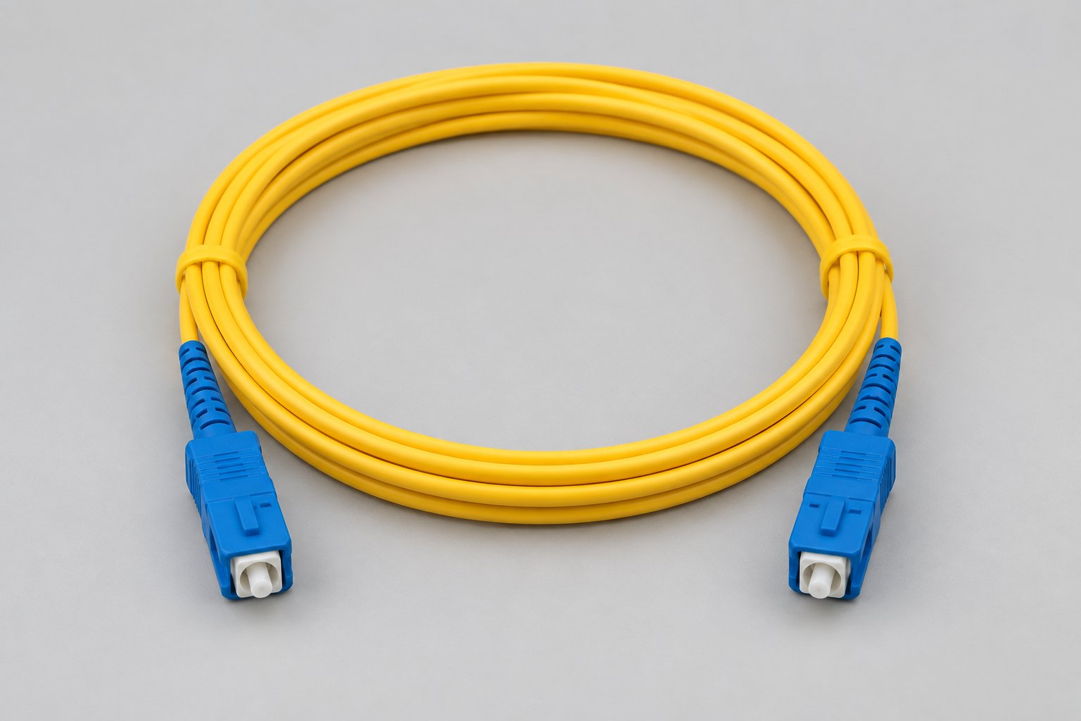
A reputable supplier will provide test results for each sample cord, but you should verify a subset yourself if you have the equipment. Select at least two or three cords of each type, clean every connector before testing, and measure insertion loss against a reference you trust. A typical single mode patch cord should show insertion loss well under its datasheet maximum — for example, SC-SC single mode G.652D cords are usually specified at 0.5 dB or better per cord, while higher-grade LC duplex cords commonly specify 0.3 dB max with return loss of 50 dB or more. These figures are typical, subject to datasheet, but a sample that measures near its stated limit is worth questioning: production cords will vary, and a marginal sample suggests the average production unit may sit even closer to the ceiling. Return loss matters as much as insertion loss for anything riding on high-speed optics, so record it where your meter supports it. Always clean connectors before each measurement, and re-inspect the end-face under a scope — a contaminated test result looks identical to a defective product. Our article on how to clean and inspect fiber optic connectors covers the procedure your team should follow both in the lab and on site.
For reference, a standard single mode patch cord sample should look like this:
Inspect Boot, Crimp, and Strain Relief Quality
Grip the cable near each connector and apply firm, steady pulling force by hand. The jacket must not slide out of the boot, and the crimp ring (where present) should hold the cable firmly without cutting into it. Flexible boots should return to shape after bending; stiff or split boots indicate over-molding problems that will crack in cold weather or repeated handling. Check that the bend radius protection at the boot is adequate for the fiber type, especially on pigtails, where the 250 µm or 900 µm buffered fiber leaves the connector body with little reinforcement. A connector that passes optical testing but fails mechanically will not survive a real installation crew.
Evaluate Pigtail Samples for Splicing Performance
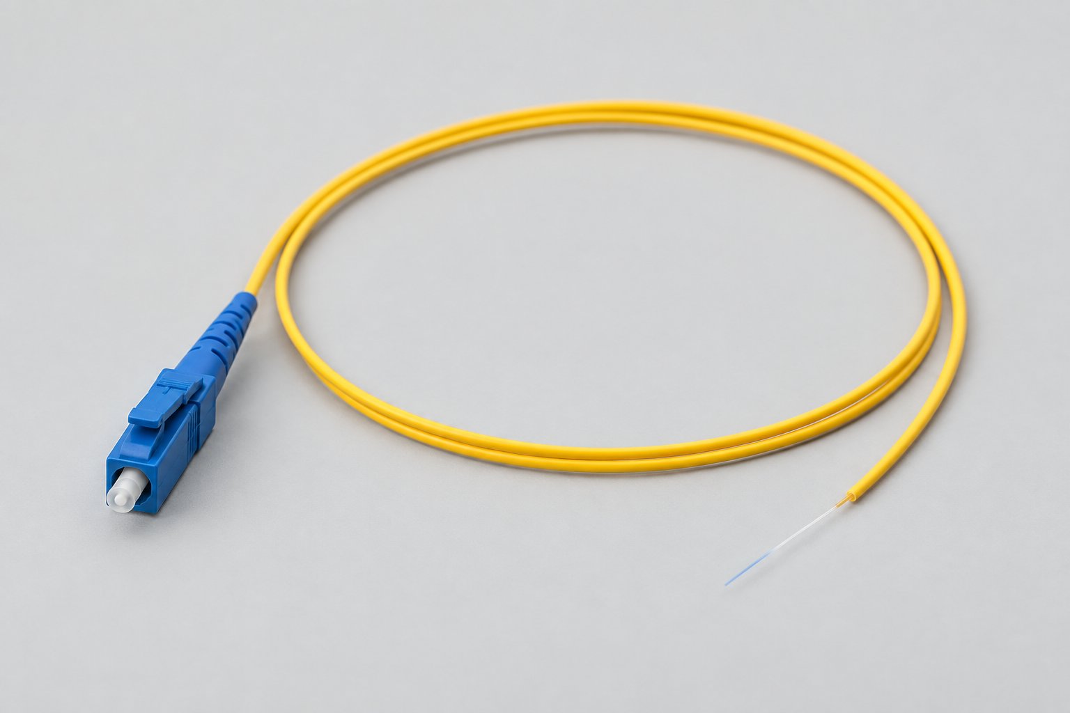
Pigtails differ from patch cords because one end is bare fiber destined for your fusion splicer. Examine how the bare fiber is protected during packaging: it should be secured so it cannot flex at the connector ferrule, and the buffer should strip cleanly without cracking the glass underneath. If possible, strip and cleave one pigtail fiber and inspect the cleave angle — a fiber that shatters or chips during stripping signals poor buffer adhesion or handling damage. Confirm the connector options match what you ordered; suppliers such as Nexora offer pigtails in SC, LC, and FC variants with one connector and one bare fiber end, designed for fusion splicing in ODFs and patch panels. A sample pigtail that splices cleanly and holds good loss after splicing is worth far more than a datasheet claim. A typical example of what you should receive:
If you are deciding between cord types for specific network segments, comparing a SC-SC single mode patch cord against a dedicated fiber optic pigtail sample side by side helps clarify which termination approach suits each part of your build.
Run a Pilot: Splicing, Termination, and a Short Field Trial
Individual tests on individual components answer narrow questions. A pilot run answers the question that actually determines project success: can your crew, using this supplier's products, build working links at production speed with acceptable yield? A pilot does not need to be large. Ten to twenty splice points, a few terminated patch cord runs, and one assembled segment are usually enough to expose problems that no datasheet or bench test reveals.
Splice the Sample Cable to the Sample Pigtails
Use the fiber from your sample cable and the pigtails from the same supplier, stripped, cleaved, and fusion spliced exactly as your field crews would do it. Record the estimated splice loss from the fusion splicer for every joint, then verify the completed splices with an OTDR or a power-meter comparison. What you are looking for is yield and consistency, not just a few good results: if two splices out of fifteen come in noticeably high, or if the splicer repeatedly struggles with the fiber's coating or cladding diameter, you have learned something important about production consistency that a single sample could never show. Where your project might use mechanical splices or pre-terminated alternatives instead, weigh the practical differences — our comparison of fusion splicing versus mechanical splicing explains how termination method choice interacts with crew skill and field conditions.
Assemble a Real Segment in a Real Enclosure
Splices in mid-air tell you about fiber quality; splices in a closure tell you about workability. If you have a spare splice closure or small wall-mount box, route the pigtail tails, store the slack, mount the splice protectors, and close everything up the way your crews will. This stage reliably surfaces issues that never show in bench testing: pigtail tails that are too short to reach the splice tray, jackets that are too stiff to route around tight corners, closure ports that do not accept the sample cable's diameter, or slack storage that forces bends tighter than the fiber tolerates. Planning your slack storage and closure layout before bulk ordering avoids redesigning mid-project; our guide on choosing a fiber optic splice closure and managing slack storage covers the geometry considerations involved.
Run the Link and Let It Sit
Once the pilot segment is assembled, test it as a complete link with an OLTS pair or an OTDR trace, and record the results. If your equipment allows, connect the link to live or simulated traffic and let it run overnight, or at least through a significant temperature swing. Stable links stay stable; a marginal connector, a fiber under excessive bend stress, or a splice with a hidden defect will often degrade over hours rather than failing immediately. Compare the next-morning readings with the initial ones. A pilot that holds its insertion loss and OTDR trace overnight gives you evidence that extends far beyond any datasheet, and it becomes a reference point you can point to if field performance questions arise after the bulk order ships.
What a Pilot Reveals That Tests Cannot
Three things emerge from a pilot that no individual measurement captures. First, tooling compatibility: whether your stripping, cleaving, and crimping tools work cleanly with this supplier's fiber diameters and connector hardware, or whether crews will fight the components. Second, handling characteristics: how the jacket behaves when pulled through duct, how the cable bends around corners at real speeds, and whether labeling survives handling. Third, yield: the percentage of terminations and splices that pass on the first attempt. A supplier whose samples produce a 95 percent first-pass yield in your crew's hands is a materially different proposition from one whose samples require rework, even if both pass every bench test. Document the pilot with photos, test traces, and notes — you will use these when turning sample results into contract terms.
Red Flags During Sample Evaluation
Most sample evaluations proceed without surprises, but certain findings should stop the process until they are resolved. None of the items below automatically means a supplier is dishonest — packaging gets crushed in transit, and documents get mismatched in busy offices. What matters is how the supplier responds when you raise the issue.
Labels or Test Reports That Do Not Match the Sample
If the test report lists a different fiber type, connector polish, or cable length than the physical sample shows, ask for a corrected report tied to the sample's serial or batch number before evaluating anything further. A mismatch may be clerical, but you cannot base a bulk decision on documents describing a different product. The supplier should be able to reconcile the discrepancy quickly and traceably; if they cannot explain which document is correct, the sample pack itself is not trustworthy.
Vague or Incomplete Datasheets
A datasheet that gives ranges instead of guaranteed values, omits test standards, or lacks mechanical and environmental parameters leaves you no contractual baseline for the bulk order. Request a complete datasheet with specified typical and maximum values, the standards referenced, and the conditions under which measurements were taken. Legitimate manufacturers produce these documents routinely; hesitation or repeated vague answers are worth treating seriously.
Refusal to Provide Test Data on the Actual Sample
Generic datasheets describe a product family; sample-specific test data describes the units in your hands. If a supplier cannot or will not provide insertion loss readings, OTDR traces, or material certifications tied to the actual sample batch, you have no way to connect your evaluation to future production. Ask directly for per-sample test results. A supplier who produces them readily is demonstrating exactly the traceability you will need on the bulk order.
Polish Type or Color-Coding Inconsistencies
An APC connector delivered where UPC was specified — or a mix of both within one sample pack — is a serious finding, because the same inconsistency can appear in production and cause silent, hard-to-diagnose link degradation across your network. Verify every connector body color and end-face angle against your order. Raise any deviation immediately and in writing, and require the supplier to confirm the corrective action in the production order.
Packaging Damage on Arrival
Crushed boxes, bent connectors, scratched ferrules, or kinked cable tell you two things at once: the packaging design may be inadequate for international freight, and the handling process may not protect delicate components. Inspect and photograph the damage on arrival, test the affected items anyway (a scratched ferrule that still meets loss spec is a different finding from one that fails), and report the condition to the supplier with photos. How the supplier responds — replacing samples, improving packaging specification, adjusting the freight method — is a direct preview of how they will handle a damaged carton inside a bulk shipment. If damage does occur in your live network later, knowing your supplier's replacement process in advance matters; our guide on emergency repair planning for damaged fiber optic cable covers how operators should prepare for these events.
Raising Red Flags the Right Way
Present findings factually and specifically: what you received, what was expected, what you measured, and what you need clarified or corrected. Avoid assuming intent, because most discrepancies have mundane causes — and avoid ignoring them, because unresolved small issues on samples have a way of reappearing at production scale. Give the supplier a defined window to respond with corrected documents, replacement samples, or written explanation, and treat their response as part of your evaluation. A supplier who addresses problems quickly and traceably has shown you something more valuable than a perfect sample pack: evidence of how they will behave across a long-term supply relationship.
From Sample Approval to Bulk Order: Turning Results into Contract Terms
A passing sample is only valuable if its results follow the order. Too many buyers approve a sample, then receive a bulk shipment that was produced to a slightly different specification — a different jacket compound, a new print legend, shorter reels, or connectors from a different batch. None of these may be outright defects, but each one changes how the cable behaves in your project. The fix is to freeze the validated configuration into your purchase order so the bulk goods are contractually the same product you tested.
At minimum, your PO or attached specification sheet should lock down:
- Fiber type and fiber count (e.g., G652D single-mode, 24 cores)
- Cable construction and jacket material (armored or all-dielectric, PE or LSZH, indoor or outdoor rating)
- Print legend wording, repeat interval, and meter marking
- Reel lengths and tolerance (for example, 2 km + 0/+5%, or custom cut lengths)
- Connector types, polish (UPC or APC), and boot style for patch cords and pigtails
- Test acceptance criteria, referenced to the sample results: attenuation per km, return loss, and which test report format accompanies each shipment
If your sample was tested against specific values — say, attenuation within a certain range or a minimum return loss on APC connectors — reference those numbers directly in the acceptance criteria rather than leaving it to "industry standard." This gives both sides an objective basis if a bulk shipment is ever disputed.
Three operational terms are worth stating explicitly in the order:
- QC reporting per shipment. Ask that the same report format used for your sample — reel-level attenuation readings, connector test data where applicable — ships with the bulk goods. A supplier with a structured pre-shipment QC process can usually accommodate this; you can see what a documented factory QC flow covers in Nexora's article on how fiber optic cable and patch cord quality is verified before shipment.
- Packing and reel handling. Reel size, drum winding, outer packing, and labeling affect whether cable arrives usable, especially for long-haul export shipments. Set expectations up front using the checklist in the buyer's guide to cable packing, reels, and delivery inspection.
- Warranty scope. Confirm the warranty period and what it covers before the PO is signed. Nexora's warranty on all products is 12 months from shipment date; for a clear picture of what such a term does and does not cover, read what a 12-month warranty really covers for fiber optic buyers.
Finally, keep your sample archive. Retain one sealed length of the approved sample, the test reports, and the document set. If a future shipment or a follow-up order needs verification, you have a physical and paper baseline to compare against. The document set you assembled during review also feeds directly into project handover; the guidance on documentation to require for a fiber optic project handover shows how those records serve you long after delivery.
One more practical point: bulk quantities change the logistics picture. Minimum order quantities, production lead time, and shipping mode all interact, and it is easier to align them while the order is being written than after it. The article on MOQ and lead time when ordering fiber optic cable and patch cords covers what to confirm with the supplier at this stage.
A Practical Sample Validation Timeline
How long validation takes depends on supplier responsiveness, shipping mode, and how much testing you do in-house — so agree on durations with your supplier up front rather than assuming them. What you can plan precisely is the sequence and, above all, who owns each stage. The table below lays out the typical flow from first request to signed PO.
| Stage | Typical Owner | Key Output |
|---|---|---|
| Request and document review | Buyer procurement/engineering, with supplier | Complete sample pack received; datasheet, test reports, and certificates reviewed and questions resolved before the cable is touched |
| Arrival inspection | Buyer QC or receiving team | Visual and mechanical checks completed; packaging, print legend, construction, and connector condition recorded with photos |
| Optical testing | Buyer lab or field engineers | OTDR and insertion loss / return loss results documented and compared against datasheet and factory reports |
| Pilot termination | Buyer splicing/termination crew | Splice loss and connectorization results from a real crew; workability and accessory fit confirmed on site |
| Decision and PO freeze | Buyer management, with supplier sales | Approved/rejected decision recorded; validated configuration, acceptance criteria, QC reporting, packing, and warranty terms written into the PO |
Note that the "decision and PO freeze" stage is where most of the value is captured. If any stage produced findings that need correcting — a print legend change, different reel lengths, an extra test in the QC report — resolve them in writing before production starts, not after the goods ship.
Frequently Asked Questions
Who pays for samples and freight?
Practices vary by supplier, sample type, and order value. Short patch cord samples are often supplied free or at low cost, while drum lengths of outdoor cable carry real material and freight cost, and courier charges for heavy reels can be significant. Ask the supplier directly whether sample cost and freight are charged, credited against a later bulk order, or waived above a certain quantity — and get the answer in writing with the sample offer. Treat the commercial terms as part of the evaluation, not a side detail.
Do sample results apply to a different fiber count or configuration?
Only partially. A 12-core sample and a 96-core version of the same cable family share fiber, materials, and process, but a higher core count changes the buffer tube layout, stranded geometry, and sometimes the outer diameter and bend behavior. If you intend to order a configuration different from the one you sampled, either request a sample of that exact configuration or confirm with the supplier which test results carry over and which need re-verification. The same logic applies to polish types: APC and UPC patch cords should each be validated on their own.
How many samples should I test?
Test enough to see consistency, not just a single lucky unit. For patch cords, a small handful across different lengths gives you a realistic read on connector quality. For cable, at minimum test both ends of each sampled length, and if the supplier sends multiple reels, check at least one length per reel. Multiple units matter because connector return loss and splice performance vary unit to unit — a single passing sample tells you far less than three or four consistent ones.
Does a passing sample guarantee every reel in the bulk order?
No, and it should not be treated as if it does. A sample validates the design, process, and supplier's reporting accuracy; it cannot guarantee each production reel. That is why the bulk PO should require per-shipment QC reports in the same format as the sample, and why incoming inspection on the bulk delivery matters. If the supplier's bulk reports start deviating from the sample baseline, that is exactly the signal to inspect before deploying.
What should I do when the bulk order arrives?
Repeat the arrival inspection you performed on the sample, scaled to the shipment: check packing and reel condition, verify print legend and lengths against the PO, and review the accompanying QC reports against your agreed acceptance criteria. Then spot-check optically — a few reels, a few patch cords — before releasing goods to the warehouse or to crews. Store cable correctly while it waits for installation; mishandled warehouse storage causes avoidable losses, as covered in the guide to storing fiber optic cable in your warehouse. Any discrepancy should be raised with the supplier promptly, while the shipment documentation is complete and the warranty window — 12 months from shipment date — is at its start.
Requesting Samples from Nexora
Nexora supports sample evaluation across its core product lines. For outdoor plant projects, buyers can request lengths from the outdoor G652D single-mode fiber optic cable range; for environments that demand extra mechanical protection, the armored fiber optic cable family can be sampled in the construction you plan to order. For termination-heavy deployments, SC-SC single-mode G652D patch cords are available with UPC/APC options and custom lengths, so you can validate the exact connector configuration you intend to buy. Custom requirements — fiber count, jacket type, reel lengths, print legends — can be handled through Nexora's OEM/ODM support, which makes it straightforward to sample the true production configuration rather than a close approximation.
To make your sample request efficient, include the following in your first message:
- Product type and application (aerial, duct, direct burial, indoor riser, patching)
- Fiber type, fiber count, and required standard or datasheet reference
- Construction and jacket requirements, including any armored or LSZH needs
- Sample lengths or quantities per item, and connector type/polish for cords and pigtails
- Destination country and preferred shipping mode, so freight terms can be quoted
- Any acceptance criteria or test reports you want the sample pack to include
The more complete your request, the closer the sample matches the eventual bulk product — and the more your validation work counts. If you are still shaping the specification, the guide on what information to include in a fiber optic cable RFQ will help you structure the request so suppliers can quote and sample accurately.
Every Nexora product is covered by a 12-month warranty from shipment date, and cable and patch cord quality is verified before shipment through the factory's own QC process — so the reports you receive with your sample should mirror what accompanies the bulk order.
Your next step: send Nexora a sample request with your target configuration, quantities, and acceptance criteria, and once the sample arrives, work through the stages in this article — document review, arrival inspection, optical testing, and a pilot termination — before writing the validated configuration into your purchase order. Doing that sequence once, thoroughly, is what turns a sample from a courtesy into real protection for your bulk order.