
Most 1G/10G to 40G/100G upgrades can run on the existing fiber. This guide explains how to identify your fiber type, calculate a loss budget, test connectors, and decide when replacement is actually required.

The Short Answer: Usually the Cable Stays, the Channel Gets Checked
When a network is upgraded — 1G to 10G, 10G to 40G or 100G, or a shift to new optics — the first question most buyers ask is whether the fiber already in the ground, in the duct, or in the ceiling has to be pulled out and replaced. In the majority of cases the answer is no: the installed cable itself stays, and what actually has to be verified is the channel — the complete optical path including the fiber, its length, its attenuation, the connectors and splices along the way, and whether the transceivers you plan to use can reach over that path with acceptable margin.
This distinction matters because replacement decisions are expensive at different scales. Replacing an outdoor buried cable means civil works, permits, outage windows and weeks of scheduling. Replacing a set of patch cords and adapters in a patch panel means an afternoon of work and a modest purchase order. The practical approach is therefore a sequence: first verify the channel against the requirements of the new transceivers, and only when a specific element fails that check, replace that element — often just the patch cords, the adapters, or a short indoor section — rather than the whole route.
The verification is not optional, though. An upgrade that skips it can end with a link that negotiates at reduced speed, shows intermittent errors, or fails entirely on a cold morning. Each of the five elements of the channel check has a defined acceptance method, and each one is covered later in this article. The short answer, restated as a decision rule: the cable stays unless the channel test gives you a concrete reason to change something, and the reason will usually point at a specific, cheap, replaceable component.
It is also worth being honest about the limits of the answer. If the installed fiber is multimode and the upgrade targets long-reach single mode optics, or if the fiber type cannot be identified at all, replacement of a section — or re-termination with new cords — becomes a real possibility rather than a fallback. Identification is the subject of the third section below.
Why the Installed Cable Is Rarely the Bottleneck
The reason existing outside plant usually survives an upgrade is simple: fiber designed around the ITU-T G.652D standard carries very little loss per kilometre, and the loss budget of a modern transceiver is sized to tolerate far more than that fiber contributes. As a reference point, the outdoor G.652D single mode cable manufactured by Nexora lists attenuation of ≤0.36 dB/km at 1310 nm and ≤0.22 dB/km at 1550 nm (IEC 60793-1-40 measurement method, as listed values). These are typical industry reference figures for this fiber class, and actual values for a specific reel are subject to the cable datasheet.
Consider what those numbers mean for an 8 km route — a common metro, campus-interconnection or FTTx feeder length. The fiber alone contributes roughly 2.9 dB at 1310 nm. A 10G LR-class transceiver is typically budgeted by its manufacturer to tolerate several times that figure across the whole channel. The fiber, in other words, is rarely where the budget goes; connectors, splices and margins consume far more of it, and those are the items a channel test will actually flag.
Where those losses actually sit is worth noting before any numbers: on a route of this length, connectors and splices together can account for more than a third of the total channel loss even though they occupy metres, not kilometres, of the path. A worked example later in this article, in the section on the loss budget, puts exact figures on that pattern and shows why a marginal upgrade usually fails at a connector pair rather than at the buried cable.
Two conditions keep this reasoning honest. First, any loss budget built from typical reference values is a design estimate; it is not a substitute for measuring the installed channel with a light source and power meter or an OTDR, which is the acceptance method described later in this article. Second, the G.652D attenuation figures are listed values for a specific product line, not a certification of every cable installed in the field. Older or damaged sections, water ingress into loose tubes, or a mid-route repair done years ago with mismatched fiber can all raise real attenuation above the reference. That is exactly what the channel test is for: it measures the route you actually have, not the route the original design assumed.
There is one more reason the installed cable is rarely the bottleneck at moderate speeds: single mode fiber has no bandwidth-distance penalty comparable to multimode's. For G.652D, the practical reach limit at 1G to 10G comes from the transceiver's designed budget, not from dispersion or fiber grade. At 40G/100G over single mode with LR/ER-class optics, the same principle holds at longer distances. Multimode installations behave differently — OM3 and OM4 have distinct distance limits per Ethernet class, and an upgrade that changes the optical standard can push a multimode link past its limit even though the fiber is perfectly healthy. That is a fiber-type question, not a loss question, and it leads directly to the identification step.
First, Identify the Fiber You Actually Have
Before any channel test or replacement decision, you need to know what glass is in the route. In many networks — especially ones inherited through acquisitions, contractor handovers or years of small extensions — the documentation is incomplete or simply wrong. Identification is mostly a desk job followed by a short site walk, and it prevents the most expensive kind of mistake: specifying an upgrade around a fiber type that turns out not to be there.
Start with the jacket print and reel labels
Outdoor and indoor cables carry periodic printing along the jacket: manufacturer, fiber type or standard designation (for example "G.652D"), fiber count, year of manufacture, and frequently a meter or length marking. On a routed cable the print repeats every metre or so, so a section visible in a manhole, at an entry point, or in a patch panel usually reveals the fiber class without any dismantling. Reel labels and original delivery documents, if archived, give the same information plus the original attenuation data. If the print is illegible on the accessible sections, note that as an open condition — the identification then has to come from the other methods below, and the result should be treated as provisional until confirmed.
Read the color code
Fiber count and position inside the cable follow a standardized color sequence, which matters when you need to locate a specific fiber pair for testing or re-termination. The conventional scheme and its on-site use are covered in detail in our article on the fiber optic cable color code. For identification purposes, two practical points suffice: loose-tube cables with a colored-tube structure and ribbon cables follow different conventions, and confirming the count and tube layout against the original datasheet is part of the same check. When the as-built count differs from the drawing, the drawing loses — record the actual state.
Single mode or multimode — jacket color and glass
The coarsest and most consequential classification is single mode versus multimode, because it decides which transceiver families the route can support at all. Jacket color is the first indicator: yellow jackets conventionally mark single mode patch cords, while orange (OM2 and below), aqua (OM3/OM4) and lime green (OM5) mark multimode. Bulk cable jackets follow similar conventions, though they are conventions, not guarantees — always confirm. The full comparison of reach, cost and use cases between the two fiber families is in our article on single mode vs multimode fiber.
Within multimode, the grade matters as much as the family, because OM3, OM4 and OM5 support different distance limits for the same Ethernet class. An aqua jacket tells you the fiber is laser-optimized multimode but not whether it is OM3 or OM4; if the upgrade targets 40G or 100G over existing multimode, the grade determines the achievable link length. How the grades differ and when each is worth specifying is covered in our article on OM3 vs OM4 vs OM5. Where the jacket print omits the grade — as it often does on older installations — treat the grade as unconfirmed and plan the channel test to measure the actual reach behavior rather than assuming a nominal limit.
Check the original datasheet — and what to do when it is missing
If the original cable datasheet survives in project files, it answers everything at once: fiber standard, attenuation at the relevant wavelengths, fiber count, tube structure, jacket material and the manufacturer's listed values. Knowing how to extract the decision-relevant rows from such a document is covered in our guide on reading a fiber optic cable datasheet. When no datasheet exists, the jacket print plus a measured attenuation figure from a light source and power meter or an OTDR serve as the practical substitute: the print identifies the class, and the measurement tells you whether that class of fiber, in its current installed condition, still fits the new transceiver's budget.
The output of this identification step should be a short written summary per route: fiber type and grade (or "unconfirmed"), fiber count, approximate length, connector types at each end, and jacket print transcription where available. Every subsequent decision in this article — the channel test, the loss budget calculation, the accept-or-replace verdict — references that summary. If the identification ends with "multimode, grade unknown, 40G target", the honest conclusion is that a section of the route or its patch cords may need replacement, and the next step is to test before ordering anything.
The Three Limits That Decide Whether an Upgrade Fits
When a network moves from 1G or 10G to higher speeds, the first question is rarely whether the fiber exists — it is whether the existing fiber plant can support the new optics under the specific standard you plan to deploy. Three physical limits decide this, and they are worth checking in a fixed order because each one fails differently. First, attenuation: if the total loss between transmitter and receiver exceeds the optical power budget of the transceiver, no amount of planning elsewhere will help. Second, dispersion and fiber grade: chromatic and modal dispersion limit how far a given signal can travel at a given data rate, which is where single mode versus multimode and OM3/OM4/OM5 distinctions matter. Third, connector and polish compatibility: a physically mated but wrongly polished pair (UPC to APC, or vice versa) causes high return loss and unreliable links even when everything else looks correct. This section works through Limit 1 in detail with a worked loss budget calculation; the following sections address the other two.
Limit 1 - Attenuation and the Loss Budget (with a worked example)
Every optical transceiver has a power budget: the difference between what its transmitter launches and what its receiver can detect at the required bit error rate. That budget is published in the transceiver datasheet, and it is the number your link must fit inside. The link's total loss is the sum of four contributors: fiber attenuation per kilometer, mated connector pairs, fusion splices, and spare margins for aging, re-matings and future repairs. If the sum of the first three, plus the margins you choose, stays below the transceiver budget, the link is viable on paper; if not, you need better fiber, fewer connections, different optics or an intermediate amplification or regeneration point — and it is far cheaper to discover this in the design phase than after installation.
Fiber attenuation is the dominant term on longer runs. For outside plant cable, Nexora lists its outdoor G.652D single mode cable at ≤0.36 dB/km at 1310 nm and ≤0.22 dB/km at 1550 nm (listed values per IEC 60793-1-40). Connector and splice losses are where discipline matters most: a mated single mode connector pair is typically budgeted at up to about 0.5 dB in conservative link designs, and a fusion splice at around 0.1 dB — these are typical industry reference values used for planning, not guarantees, and actual field performance should be verified against the transceiver and cable datasheets.
To show how the arithmetic works, here is a clearly hypothetical example. Assume an 8.0 km single mode channel on G.652D fiber at 1310 nm, upgraded to a 100G LR-class optic with an assumed typical power budget of 6.3 dB — the real value must come from the specific transceiver datasheet you plan to buy. Assume two mated connector pairs (for example, one at each end plus a patch panel crossing) and four fusion splices along the route:
| Component | Quantity | Typical planning value | Loss contribution |
|---|---|---|---|
| Fiber attenuation (G.652D @ 1310 nm) | 8.0 km × 0.36 dB/km | 0.36 dB/km | 2.88 dB |
| Mated connector pairs | 2 | 0.5 dB per pair | 1.00 dB |
| Fusion splices | 4 | 0.1 dB each | 0.40 dB |
| Channel total | — | — | 4.28 dB |
| Assumed transceiver budget | — | — | 6.30 dB |
| Design margin | — | — | 2.02 dB |
| Aging / repair allowance | — | 1.00 dB | −1.00 dB |
| Margin after aging | — | — | 1.02 dB |
In this hypothetical case the link fits, but only just: after reserving 1.00 dB for aging, additional connector matings and future repairs, roughly 1 dB of headroom remains. That is a workable but tight result. If the same channel ran at 1550 nm with lower attenuation, the margin would improve; if the route gained two more panel connections or a couple of extra splices, the margin could drop close to zero, which is the point at which an upgrade that looked fine on a datasheet becomes a field problem.
Three practical points follow from this. First, count every mated pair on the actual route, including patch panels and test equipment connections — connector loss accumulates faster than fiber loss on short-to-medium links. Second, always pull the power budget from the transceiver datasheet you intend to purchase; assumed budgets are for illustration only, and different optic classes and vendors specify different values. Third, remember that patch cord quality affects two of the three connector-dependent rows: a cord specified at ≤0.3 dB maximum insertion loss per cord (as listed for Nexora's LC-LC duplex single mode G.652D patch cords, with ≤0.2 dB typical across production) uses up less of your margin than an unspecified cord. For a full step-by-step treatment of building these budgets, see our guide to calculating a fiber optic link loss budget, and for interpreting the transceiver and cable documents that supply the input numbers, see how to read a fiber optic cable datasheet before you buy.
Limit 2 – Dispersion and Bandwidth
Attenuation is only half the story. The second limit is dispersion – the spreading of light pulses as they travel – and it determines whether a link can carry a higher lane rate at all, regardless of how little optical power is lost along the way.
On single mode fiber, the relevant mechanism is chromatic dispersion: different wavelengths travel at slightly different speeds, so a short pulse broadens over distance. The effect grows with transmission rate, with the wavelength used, and with the spectral width of the transceiver's laser. This is why a G.652D link that carries 1G or 10G comfortably over several kilometers may need dispersion compensation, a narrower-linewidth laser, or a shorter reach rating when you move to 25G or higher lane rates on the same fiber. The fiber itself does not change; what changes is how much pulse spreading the transceiver can tolerate. G.652D is optimized for the 1310 nm and 1550 nm windows – the Nexora outdoor G.652D cable is specified with an MFD of 9.2 ± 0.4 µm at 1310 nm and a cable cutoff ≤1260 nm as listed values – and it is the standard choice for outside plant. Whether a specific transceiver reaches a specific distance at a specific rate is a datasheet question: always check the reach table on the transceiver and cable datasheets rather than assuming an old link can simply be re-rated.
On multimode fiber, the ceiling is modal bandwidth: light launched into a multimode core takes multiple paths, and the path-length differences smear pulses. The fiber grade sets that ceiling. OM3 is specified to support 10G transmission over 300 m at 850 nm as a typical channel-design reference, subject to the transceiver datasheet; OM4 and OM5 extend the usable distance and, at 40G/100G with parallel or duplex optics, determine which reach class you can order. The practical consequence for an upgrade: if your existing multimode plant is OM2 or older, no transceiver choice will make it behave like OM4. The grade of the glass is the ceiling; the optics decide how close you get to it. If you are re-specifying multimode cabling rather than reusing it, the trade-offs between grades are covered in our comparison of OM3, OM4 and OM5.
Two decisions follow from this limit. First, identify the fiber type in the existing plant before quoting an upgrade – the color jacket and cable markings usually identify it, and our color code guide shows how to read them on site. Second, match the transceiver's specified fiber grade and reach to what you actually have; a transceiver rated for OM4 at a given distance will not deliver that distance over OM3.
Limit 3 – Connector Quality and Return Loss
The third limit lives at the smallest scale: every mated connector pair adds loss and reflects some light back toward the transmitter. A short patch link may have negligible fiber attenuation yet still fail, purely because of connector quality.
Insertion loss (IL) is the power lost where two ferrules meet. Each patch cord is specified with a maximum IL per cord, and every mated pair in the channel – patch panels, adapters, transceiver ports – contributes its share. Lower IL per component leaves more of the loss budget for the actual fiber run, which matters most on longer single mode links. As a reference for what a manufacturer should commit to, Nexora lists its LC-LC duplex single mode G.652D patch cord at ≤0.3 dB maximum insertion loss per cord as a release limit, with ≤0.2 dB typical across production, tested at both 1310 nm and 1550 nm; these are the product sheet's listed values, and equivalent figures should be requested for any cord you buy. How to read them in detail is explained in our guide to patch cord specs.
Return loss (RL) is the mirror problem: the fraction of light reflected back into the transmitter. High reflections degrade laser stability and error rate, particularly at higher rates and on GPON and CATV links. Polish type sets the floor: a UPC ferrule is typically specified at ≥50 dB return loss on single mode cords, while an APC ferrule, with its angled 8° polish, achieves substantially higher return loss and is the standard choice for FTTH and RF overlays. The two are not interchangeable – mating an APC plug to a UPC adapter or cord leaves an air gap and a severe loss penalty, so a mixed polish field is a real operational risk, not a cosmetic one. The mechanical details and selection logic are covered in our UPC vs APC explainer; Nexora lists the LC-LC duplex single mode UPC cord at ≥50 dB return loss on its product page, and offers APC-poled cords and dedicated APC adapters where the network requires them.
For an upgrade, the actionable check is simple: count every mated connector pair in the channel, assign each a loss value from the manufacturer's datasheet, and confirm that every polish type in the path matches. Contamination and end-face condition dominate real-world connector loss, so cleaning and inspection before measurement is part of the method described in the next section.
What Actually Changes Between 10G, 40G and 100G
When a network moves from 10G to 40G or 100G, the fiber itself usually matters less than the optics and the geometry of the link. The clearest way to see this is to compare published reach figures for common IEEE-style transceiver classes. The table below collects typical industry reference values; always confirm the actual reach for your chosen optic against the transceiver datasheet, since vendor-specific variants differ.
| Transceiver class | Fiber type | Typical reach reference |
|---|---|---|
| 10GBASE-LR | Single mode (G.652D) | ~10 km |
| 10GBASE-ER | Single mode (G.652D) | ~40 km |
| 100GBASE-LR4 | Single mode (G.652D) | ~10 km |
| 100GBASE-ER4 | Single mode (G.652D) | ~40 km |
| 10GBASE-SR | OM3 multimode | ~300 m |
| 10GBASE-SR | OM4 multimode | ~400 m |
| 40GBASE-SR4 | OM3 multimode | ~100 m |
| 40GBASE-SR4 | OM4 multimode | ~150 m |
| 100GBASE-SR4 | OM3 multimode | ~70 m |
| 100GBASE-SR4 | OM4 multimode | ~100 m |
Two patterns emerge from these figures. First, on single mode the reach barely changes: 10GBASE-LR and 100GBASE-LR4 both target roughly 10 km, and the ER-class optics both target roughly 40 km. A 100G upgrade across a campus or metro span built on G.652D is therefore largely a transceiver decision, not a cabling decision — the same outdoor cable that carried 10G carries 100G at the same reference distances. If you are evaluating cable for those longer spans, the attenuation and MFD values on the datasheet matter more than the speed class; our guide on how to read a fiber optic cable datasheet before you buy walks through those parameters line by line.
Second, on multimode the reach collapses as the data rate per lane rises. OM3 supports roughly 300 m at 10G but only about 70 m at 100GBASE-SR4; OM4 goes from roughly 400 m down to about 100 m. The fiber has not degraded — the physics has changed. Higher serial rates suffer more from chromatic and modal dispersion within each lane, so the usable distance per lane shrinks. Anyone planning a data center upgrade over existing OM3 should measure actual runs before assuming 100G will close the link; our comparison of OM3, OM4 and OM5 grades explains how each step up in grade buys back some of that budget.
Multimode Reach Shrinks Faster Than You Expect
The reason multimode reach drops so sharply is architectural, not just optical. 10GBASE-SR uses one serial lane at 10 Gb/s. 40GBASE-SR4 splits traffic across four parallel lanes over a ribbon-style fiber pair, and 100GBASE-SR4 across ten lanes (or, in modern two-lane optics, two 50G lanes). Each lane gets its own smaller loss and dispersion budget, and that per-lane budget is where connector loss starts to bite.
Consider what this means numerically. A single mated connector pair on a well-made patch cord contributes a fraction of a dB — Nexora lists a maximum insertion loss of 0.3 dB per cord, with production running typically at or below 0.2 dB, which is consistent with common industry practice. On a 10G serial link with a generous power budget, one or two extra connector losses are an annoyance. On a 100GBASE-SR4 lane with perhaps only a few dB of total headroom over its ~70–100 m reference reach, the same connectors consume a meaningful share of the entire budget — and they do so on every lane independently, so one weak lane limits the whole parallel link.
This is also why MPO/MTP connectors dominate high-density 40G/100G multimode cabling: a single multi-fiber connector lands eight, twelve or twenty-four lanes at once, replacing rows of duplex cords. But MPO brings its own disciplines — polarity conventions (A, B and C methods), fan-out structure and pin alignment — and a polarity mistake does not produce a marginal signal, it produces a dead link. If you are selecting multi-fiber cords, our article on choosing MPO/MTP patch cords for high-density data center cabling covers polarity and inspection in detail.
Practically, three habits keep parallel multimode links inside budget. First, count every mated pair in the channel, including patch panels at both ends and any interconnects in between, and sum their worst-case insertion losses before committing to a transceiver class. Second, prefer fewer connections over more: a structured backbone designed for 100G often consolidates what were separate 10G cross-connects. Third, remember that modal bandwidth grades are not interchangeable — an OM3 run measured at 65 m may pass at 100G, but a 90 m OM3 run that worked fine at 10G will not. Our single mode versus multimode comparison is useful if the run lengths in your building make you question whether multimode is still the right medium at all.
The Components That Usually Do Need Replacing
While the installed backbone cable often survives a speed upgrade, the peripheral components frequently do not. Budget for these four categories before the transceiver order goes out.
Patch cords
Patch cords are the most common replacement item, for two reasons. On multimode, 40G/100G optics expect specific lane counts and fiber grades, so duplex OM3 or OM4 cords in front of new optics often need to become OM4 (or stay OM4 with the correct length margin). On single mode, an upgrade is less disruptive, but worn, dirty or mismatched cords are the first suspects when a link margin disappears.
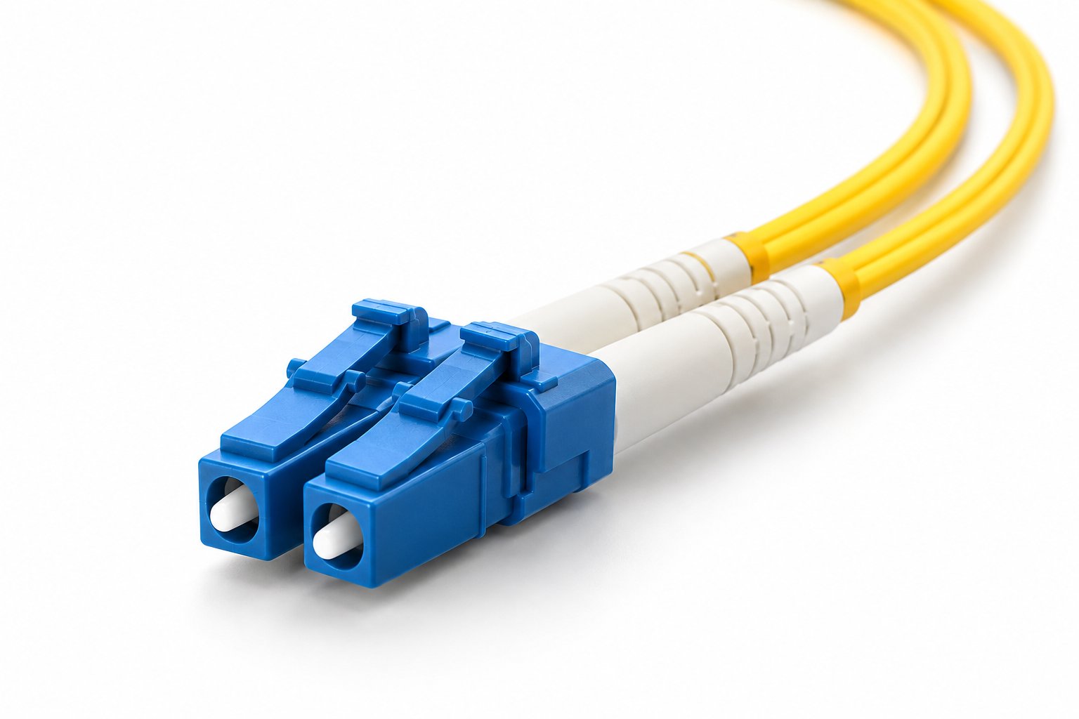
Match the cord to the channel, not just to the connector type. Nexora's LC-LC duplex single mode G.652D patch cord is tested at both 1310 nm and 1550 nm, with UPC end faces, a listed return loss of ≥50 dB, and ≤0.3 dB maximum insertion loss per cord (≤0.2 dB typical across production); jackets are available in LSZH or PVC at 2.0/3.0 mm OD with custom lengths from 0.5 to 30 m. For multimode runs, the SC-SC duplex OM3 cord carries the same insertion loss limits and is tested at 850/1300 nm, with lengths up to 50 m; for 40G/100G links, the LC-LC duplex OM4 cord is specified for data center use with ≤0.3 dB maximum insertion loss. If your racks are a mix of SC panels and LC-based optics, the SC-SC single mode G.652D cord (UPC or APC options, ≤0.5 dB max insertion loss) covers the panel side. Polish type matters too: mixing UPC and APC in one mated pair damages both ferrules and wrecks return loss — our UPC versus APC guide explains which polish suits which network segment.
Adapters
Adapters are the second quiet culprit. If an upgrade changes the polish scheme anywhere in the path — for example, moving CATV or access legs to APC — the adapter in the panel must match, because an APC ferrule seated in a UPC adapter leaves an air gap and destroys return loss. Nexora offers an LC/APC duplex adapter for high return loss APC connections and an SC/APC adapter for FTTH, CATV and access networks. When the upgrade keeps UPC throughout, existing adapters only need inspection and cleaning; our connector cleaning and inspection guide covers the procedure and the pass criteria.
Pigtails and panel terminations
At the ODF and patch panels, spliced pigtails are where the plant meets the patchfield. A speed upgrade does not force pigtail replacement if the splice loss is still in spec, but panels being reorganized for higher density usually get re-terminated anyway, and that is the right moment to standardize connector types and lengths. Nexora's fiber optic pigtail is available with one connector plus a bare fiber end for fusion splicing, in SC, LC and FC options. Verify splice results with an OTDR rather than trusting the fusion machine's estimate; our OTDR acceptance testing guide shows how to document results for handover.
Polarity and documentation
Finally, the least physical item is the one that causes the most callbacks: polarity and labeling. Parallel optics (SR4 and friends) are unforgiving of a crossed transmit/receive pair, so any patch cords bought for a 40G/100G upgrade should follow a declared polarity convention across the whole channel, documented in the as-built records. Color coding helps enforcement — the fiber color code article covers how fiber and connector colors map to grades and polish types on site, so a contractor can spot an OM3 cord hiding in an OM4 link at a glance.
A sensible procurement step is to fold these components into the cable RFQ as one line item per type, with quantities tied to the actual port counts in the upgrade plan, rather than discovering mid-installation that forty LC/APC adapters or a batch of correctly-polarized MPO trunks are missing. For long single mode spans that do need new cable rather than just cords, Nexora's outdoor G.652D cable (2–288 cores, gel-filled loose tube, listed attenuation ≤0.36 dB/km at 1310 nm and ≤0.22 dB/km at 1550 nm) ships on 2/4/6 km wooden drums with dispatch typically 15–20 working days. All Nexora products carry a 12-month warranty from shipment date, and patch cord orders start at an MOQ of 100 pcs per configuration.
Clean, Inspect and Re-Test Before and After the Upgrade
Most fiber link upgrades are completed on the passive plant you already have, which means the two failure points you control directly are the end faces of every connector in the path and the accuracy of your before/after measurements. Contamination is the single most common cause of degraded connector performance on links that were otherwise sound: dust, oil from fingerprints, and residue from previous handling all raise insertion loss and depress return loss. Before you bond new optics or re-route anything, clean every mateable connector end face with a one-click cleaner or lint-free wipes and approved solvent, then inspect each face with a fiber scope. An end face that looks clean to the eye is frequently not clean under magnification, and inspection is the only way to confirm the result. Our guide to cleaning and inspecting fiber optic connectors walks through the process step by step (how do you clean and inspect fiber optic connectors).
Once connectors are clean, record the actual loss of the link before the upgrade. A light source and power meter at the wavelength your new transceivers will use gives you the true end-to-end insertion loss of the channel, which is exactly the number you need to compare against the loss budget of the higher-speed optics. If you have OTDR access, capture a baseline trace as well, so that any post-upgrade anomaly can be localized to a specific connector, splice, or cable section. After the upgrade, repeat both tests on the same reference method and compare against the baseline. Our articles on light source and power meter testing (how do you test a fiber optic link) and OTDR acceptance testing (how do you use an OTDR to accept a new installation) cover the methods in detail.
One practical caution: always test at the wavelength that matters for the upgrade. A link that passes comfortably at 1310 nm may behave differently at 1550 nm, and multimode links are designed around 850 nm for high-speed channels. Testing only at one wavelength can hide a margin problem that appears exactly where your new transceivers operate.
When the Cable Itself Really Must Be Replaced
Not every upgrade can be finished on the existing cable. Four conditions typically force replacement, and it is worth identifying them early in the planning stage rather than after optics have been ordered.
- Legacy water-peak fiber. Fiber manufactured before the low-water-peak standard was widely adopted shows a raised attenuation around the 1383 nm region, which limits its usefulness on modern wavelength plans. If the existing plant is old single mode fiber of unknown vintage, ask the cable manufacturer or check printed markings on the drum or jacket to determine whether it meets current specifications such as ITU-T G.652D. Cable installed today to G.652D carries low water-peak performance as a listed characteristic.
- Attenuation above budget. If your OTDR trace or power meter measurement shows loss that leaves no workable margin against the new optics' budget — even after every connector has been cleaned and re-terminated — the fiber itself is the problem. Aging cable, water ingress into the sheath, and kink damage from past handling all show up as distributed or localized loss that cleaning cannot recover.
- Physical damage. Crushed sections, rodent damage, jacket breaches that have admitted water, and broken strength members all require replacement of the affected section or the whole run. A localized fault can sometimes be repaired with a splice and a new section of matched cable, but repeated faults on the same route are a signal the installation conditions exceed what the cable was specified for.
- Wrong fiber type. If the installed plant is OM1 or OM2 and the upgrade target is 10G or higher over distances beyond what those grades support at 850 nm, no amount of testing changes the physics. The fiber type must match the distance and speed requirement.
For short indoor runs — a floor distributor, a data center row, a cross-connect — the fastest replacement is usually not a new cable installation at all, but factory-terminated patch cords and pre-terminated assemblies. A factory-terminated cord arrives with insertion loss and return loss already measured and documented, avoiding field termination quality as a variable. For outdoor runs, a new loose-tube cable is the right starting point; Nexora's outdoor G.652D cable is a gel-filled loose-tube design with steel wire or FRP strength member, available in 2–288 cores, with listed attenuation of ≤0.36 dB/km at 1310 nm and ≤0.22 dB/km at 1550 nm (per IEC 60793-1-40, listed values — always confirm against the datasheet for the specific order) and an operating temperature range of −40 to +70 °C. Indoors, flexible multi-core routing is handled by distribution fiber optic cable, which suits the building and data center runs between panels and equipment.
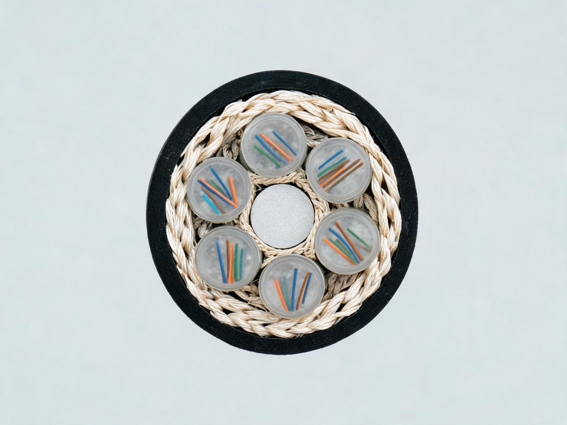
When a replacement outdoor section is spliced into an existing route, pigtails spliced onto the new cable and mounted in the ODF give you factory-quality end faces at the panel end (fiber optic pigtails), and the splice points can then be verified with the OTDR.
Adding Capacity with Wavelengths Instead of New Fiber
Where the fiber itself is sound but the fiber count is the constraint, wavelength-division multiplexing offers a path that does not involve pulling any new cable. CWDM and DWDM both work on the same mechanism: multiple transceivers, each operating on a different wavelength, are combined onto a single fiber pair through passive multiplexers at each end. Each wavelength travels independently over the same fiber, so one physical pair can carry several logical channels. CWDM uses a wider channel spacing (typically 20 nm) and uncooled optics, which keeps cost and power down and suits campus, metro, and operator access distances. DWDM uses much tighter spacing, supports more channels over the same pair, and is the usual choice for long-haul and high-density transport, at the cost of more expensive optics and tighter wavelength tolerances.
The key trade-off is optical budget: the multiplexer/demultiplexer pair adds insertion loss to every channel, and the reach of a given transceiver over a WDM configuration is shorter than its reach over a direct fiber pair. Reach numbers quoted for CWDM and DWDM transceivers are typical industry values and are subject to the transceiver datasheet — compute the budget for the actual multiplexer loss, fiber attenuation at the specific wavelength used, and connector and splice losses in the path, using the same method covered in our loss budget article (how to calculate a fiber optic link loss budget). Because the passive plant carries all channels, an attenuation or connector problem that was marginal on one service becomes a problem for every service once it is multiplexed — one more reason the cleaning and baseline testing described above matters before a WDM overlay.
What to Put in the RFQ for an Upgrade Project
An upgrade RFQ that omits details returns quotes that cannot be compared. State the following explicitly, and the supplier can quote like-for-like across configurations (what to include in a fiber optic cable RFQ):
- Fiber type and count: G.652D single mode, OM3/OM4/OM5 multimode, and the core count for cable items — not just "single mode 12-core" but the standard designation.
- Lengths per configuration: exact cord lengths and cable drum lengths you need, so the manufacturer quotes real configurations rather than a generic catalogue item.
- Connector types and polish: LC or SC, UPC or APC, and any mixing rules on adapters. APC and UPC must never be mated directly; the adapter choice follows the polish type (UPC vs APC explained).
- Polarity and duplex configuration: for 40G/100G links over duplex cords and any MPO trunks, specify the polarity method so transmit and receive land where the transceivers expect them.
- Test records required: insertion loss and return loss per cord, tested at the wavelengths of use, with results supplied per configuration.
- Jacket and environment: LSZH vs PVC for indoor cords; PE sheath and strength member type for outdoor cable.
On commercial terms, it helps to know the manufacturer's stated ordering constraints before you draft the RFQ. For Nexora patch cords, the listed MOQ is 100 pcs per configuration, with standard dispatch in 7–15 working days; outdoor cable drums are supplied in 2/4/6 km lengths with dispatch typically 15–20 working days (MOQ and lead time explained). If your project requires documented manufacturing quality, state which certifications and test reports you require in the RFQ itself (which certifications to require), and confirm the warranty terms in writing — Nexora products carry a 12-month warranty from shipment date (what the 12-month warranty covers).
Frequently Asked Questions
Can I upgrade a fiber link from 1G to 10G without replacing the fiber?
Usually yes, if the existing fiber is the correct type and the measured loss fits the 10G optics' budget. A 1G link that ran with large margin may still pass at 10G on the same plant, but the loss budget at 10G is tighter, so measure rather than assume. Clean and inspect every connector first; a link that failed at 10G but passed at 1G is often a contamination or connector problem, not a fiber problem.
Do I need to replace the fiber for 100G?
Not necessarily. Over single mode, 100G can run on G.652D within the reach limits of the chosen transceiver type. Over multimode, it depends on the grade and distance: OM4 and OM5 support 100G over shorter parallel or duplex configurations than OM3, and the exact reach is subject to the transceiver datasheet. If your installed plant is OM1/OM2 and the target is 100G, replacement is generally unavoidable.
How do I know what fiber I have if there is no documentation?
Check the cable jacket print and drum labels, which typically state the fiber designation, core count, and year. Jacket colour helps at a glance — yellow for single mode, aqua for OM3, violet for OM4, lime for OM5 — but colour alone is not proof of grade. An OTDR trace can reveal attenuation behaviour and legacy water-peak characteristics, and the cable manufacturer can interpret markings if you send them what is printed.
Is OM3 enough for 100G?
OM3 was designed around 10G over longer reaches and can support 100G in specific transceiver configurations over shorter distances, typically via parallel lanes. For duplex 100G optics, OM4 and OM5 are the usual specification. Verify the required distance against the transceiver datasheet before ordering cords, and see our OM3/OM4/OM5 comparison (OM3 vs OM4 vs OM5).
Can APC and UPC connectors be mixed on the same link?
Not at a mating interface. An APC connector has an angled, polished end face; mating it with a UPC connector leaves an air gap that produces very high loss and can damage both faces. Keep polish types consistent within each channel, use matching adapters at panels, and be aware that APC connectors have different return loss characteristics (our cord specs article covers this — reading patch cord specs).
What does an upgrade actually cost, and what drives the price?
The drivers are whether the existing fiber can be reused, the connector and polish types, the number of distinct configurations, and whether WDM equipment is added instead of cable. Reusing the plant costs mainly cleaning, testing, and new optics; adding pre-terminated cords or new cable adds configuration count and length per run. Getting exact lengths and configurations into the RFQ is what turns a range of quotes into a comparable one.
The Bottom Line
Most upgrades fail in one of two places: an unmeasured connector, or an unexamined assumption about the installed fiber. Clean and inspect every end face, baseline the link before you change anything, and test at the wavelength your new optics use; only replace cable when the fiber type, measured attenuation, or physical condition genuinely forces it — and on short runs, factory-terminated cords such as an LC-LC duplex single mode patch cord with documented insertion loss are the faster and more verifiable path. Where fiber count is the constraint rather than the fiber quality, CWDM or DWDM can add channels over the pair you already own. If you send Nexora your existing link details — fiber type, measured loss, distances, and the speed you are targeting — we can review the passive side of the upgrade against these conditions and quote the materials that fit.