
A buyer's guide comparing fiber optic cable vs copper for industrial networks: where fiber wins on EMI, distance and lifetime cost, and which cable construction fits each route.
Walk through almost any factory, utility substation, port or mining site built before 2015 and you will find the same wiring story: copper Ethernet and serial cables running from the control room out to drives, PLCs, cameras and sensors. That copper was the right answer when the traffic was small, the runs were short and the electrical environment was quiet. None of those assumptions hold reliably anymore. Variable frequency drives, welders, large motors and switch-mode power supplies fill modern plants with electromagnetic noise; video, inspection systems and machine data push traffic volumes that swamp 100 Mbps links; and the distance between a new production line and the network core keeps growing as sites expand. So the question every industrial buyer eventually faces is not whether fiber optic cable is technically superior — it usually is — but whether the economics, the installation effort and the maintenance model justify moving specific routes from copper to fiber optic cable, and if so, which routes first.
This guide is written for the people who actually make that call: plant engineers, system integrators, electrical contractors and procurement teams specifying cabling for industrial environments. It compares copper and fiber across the factors that decide real projects — electromagnetic interference, distance, bandwidth, installed cost, termination skills, and long-term operating risk — and then maps the decision onto the cable types an industrial project actually orders: outdoor loose-tube backbone cable, armored cable for direct burial and rodent-prone corridors, and tight-buffered indoor cable for the plant floor and control rooms. Performance figures quoted for fiber constructions are typical industry values; always confirm the exact limits on the datasheet supplied with your order before finalising a design.
Why the Fiber-versus-Copper Question Comes Up on Every Industrial Retrofit
Twenty years ago, an industrial network was mostly a control network: small cyclic messages between a PLC and its I/O, a few serial links, maybe an HMI panel. Cat5 copper solved that at trivial cost. The pressure to re-examine copper today comes from four directions at once, and understanding them helps you decide which parts of your network genuinely need fiber optic cable and which parts can stay on copper for years to come.
The first driver is data volume. A single modern inspection camera can generate more traffic than an entire production line did a decade ago. Condition-monitoring systems stream vibration and thermal data continuously. Energy-management and MES systems aggregate thousands of tags at second-level resolution. When a plant's backbone is built from copper runs, each new subsystem competes for the same finite uplinks, and the cheapest upgrade path eventually becomes a fiber backbone rather than another layer of copper aggregation switches.
The second driver is distance. Copper Ethernet is formally limited to 100 meters per segment regardless of cable category. That limit is not a suggestion; beyond 100 m, signal reflections and attenuation exceed what the transceivers are specified to recover. In a plant where the control room sits 400 meters from the new pumping station, a copper design must insert a powered intermediate switch or a media converter roughly every hundred meters — often in a cabinet that has no convenient power, no air conditioning and no easy access. A single fiber optic cable span covers that same 400 meters without any active equipment in between, because even at modest industrial data rates, single mode fiber is specified over many kilometers.
The third driver is the electrical environment itself. Industrial sites are among the most electromagnetic-hostile places a network cable can live, and this is where the physical difference between copper and fiber is not incremental but categorical — a point worth examining in detail, because it alone settles the decision on many routes.
Electromagnetic Interference: The Difference That Cannot Be Equalized
Copper Ethernet carries its signal as a small voltage difference between twisted pairs. Anything that couples onto those pairs — a fluctuating magnetic field from a large motor, common-mode noise riding in on a ground potential difference, the burst of a contactor opening — appears as noise in the same channel as the data. Shielded cable and careful bonding reduce the coupling, but they do not eliminate it, and their effectiveness depends entirely on installation discipline: shield continuity through every junction, correct grounding at exactly one end or both ends depending on the scheme, and separation from power trays. On a busy plant floor, all three disciplines erode over years of modifications.
A fiber optic cable carries its signal as light in a glass core. There is no metallic conductor in the optical path, so there is nothing for an external electromagnetic field to couple into. A loose-tube cable strapped to the same tray as the drive output cables, routed past a spot-welding cell, or run inside a substation fence is invisible to that interference — and equally, the fiber does not emit anything that would disturb nearby instrumentation. This is why industrial standards for motor-control centers, substations and heavy welding environments consistently point to fiber for the noise-exposed segments rather than to progressively heavier copper shielding.
The practical consequence shows up as symptom pattern, not as a specification line. Copper links in electrically noisy areas fail in characteristic ways: intermittent CRC errors that spike when a specific machine cycles, links that drop when a large drive accelerates, cameras that show corrupted frames only during welding windows. Each symptom is individually diagnosable, but collectively they consume engineering hours year after year. When a route exhibits this pattern, converting it to fiber removes the failure mode entirely rather than managing it. The table below summarizes how the two media behave across the noise-related factors that dominate industrial routes.
| Factor | Copper (Cat5e/Cat6/industrial Ethernet) | Fiber optic cable |
|---|---|---|
| EMI from drives, welders, motors | Susceptible; depends on shielding and bonding quality | Immune in the optical path; glass does not conduct or couple |
| Ground potential differences between buildings | Conductive path; risk of ground loops and equipment damage during surges | No metallic path; isolates buildings electrically |
| Surge and lightning coupling | Inter-building runs can conduct surge energy into switches | Non-conductive; standard practice for inter-building links |
| Emissions affecting nearby instrumentation | Radiates a small amount; managed by shielding | None; suitable near sensitive measurement circuits |
| Installation discipline required | High: shield continuity, grounding scheme, power/data separation | Bend radius and tensile limits; no grounding scheme needed |
One caution belongs next to this table. The optical path is immune to interference, but a fiber optic cable is not automatically immune to everything: all-dielectric constructions exist precisely so the cable adds no metallic path, while armored cables with steel tape or steel wire armor do introduce metal, which matters for grounding and for use near high-voltage equipment. Choosing the right construction for the electrical context is part of the specification work described later in this guide.
Distance and Bandwidth: Where the Physical Limits Sit
The 100-meter copper segment limit and the multi-kilometer reach of fiber are not marketing claims; they follow from the physics of the two channels, and they shape network topology more than any other single factor.
On copper, Ethernet transceivers are engineered to recover a signal attenuated and distorted over exactly 100 meters of the specified category. If your route is 320 meters, you do not buy "better copper" — you buy an active device at an intermediate point, with its own power supply, its own failure modes, its own cabinet, and one more location that has to be visited when something needs tracing at 3 a.m. A long copper chain through a plant therefore accumulates infrastructure: cabinets, switches, UPS units and patch panels, each of which is a maintenance liability long after the cable itself is forgotten.
On single mode fiber, attenuation is measured in fractions of a decibel per kilometer. A typical G.652D single mode construction is specified at ≤0.36 dB/km at 1310 nm and ≤0.22 dB/km at 1550 nm — these are typical industry values, and the datasheet issued with your reel states the acceptance limits that apply to it. Working through an example shows how much margin this creates: a 5 km run between a main control room and a remote utility building consumes about 1.8 dB of fiber attenuation at 1310 nm. Industrial Ethernet media converters and switches typically budget several decibels for the optical link, so after connectors, splices and aging margin, the route still fits comfortably — with kilometers of headroom left. On copper, the same 5 km would require roughly fifty powered segments.
Bandwidth tells the same story from the other direction. The categories of copper cable (Cat5e, Cat6, Cat6A) fix a ceiling on what the link can carry over its 100 meters, and each step up in category costs more per meter and more per port. Multimode fiber grades (OM3, OM4) and single mode fiber support 10G, 40G and 100E Ethernet with transceiver upgrades rather than cable replacement. The practical rule most industrial projects converge on: run fiber optic cable for the backbone and any route over 100 meters, and keep copper at the edges where devices sit within reach of a local switch. If you want the arithmetic behind sizing such a backbone, the guide to calculating a fiber optic link loss budget walks through the same calculation end to end.
How Do You Calculate a Fiber Optic Link Loss Budget for Your Network Design?
Distance Beyond the Building: Inter-Building and Campus Runs
Between buildings, copper has a second problem on top of reach: it forms a conductive bridge between two grounding systems. A potential difference between buildings — routine after storms, or whenever the grounding grids differ — drives current through the cable shield, and a nearby lightning strike induces surge energy that travels straight into the switches at both ends. Isolation and surge-protection hardware exists, but it is per-link, per-direction equipment that has to be maintained. This is why the standard engineering answer for any inter-building or campus link is a non-conductive outdoor fiber optic cable run: the two grounding domains simply never meet. Direct-buried and duct installation practices for such routes are covered in detail in the trenching and duct guide, and the same logic applies to aerial spans between buildings on poles.
Intrinsic Safety and Hazardous Areas
In classified hazardous areas — refinery units, grain handling, spray booths, mining surfaces — the energy that a copper cable can store and deliver matters as much as its data capacity. A copper run into a Zone 1 area carries fault energy that must be limited by intrinsically safe barriers or explosion-proof routing. Fiber introduces no electrical energy of its own: a glass waveguide carrying light cannot spark, arc or ignite. For this reason, fiber optic cable has long been the preferred medium for crossing the boundary into hazardous zones, with the network equipment kept outside the classified area and only the passive cable penetrating it. Buyers working on such projects should still confirm the specific certification scheme required by the site and local regulations; the cable being non-conductive is necessary but the certification paperwork follows its own rules.
Where Copper Still Wins: An Honest Accounting
A guide that only praised fiber would not help you budget a project. Copper retains real advantages on specific segments, and pretending otherwise produces designs that overspend on fiber where it adds nothing.
Short runs at the edge. Connecting a cabinet of drives to the switch three meters away is a solved problem for copper. The cable is cheap, the RJ45 termination takes seconds, and every electrician on site can do it. Fiber at the edge buys immunity you do not need and costs a transceiver at each end.
Power over Ethernet. Many industrial devices — IP cameras, wireless access points, some I/O adapters — take their power over the same copper pair that carries data. Fiber cannot deliver power. A fiber-fed camera requires a local power source or a hybrid cable approach, which adds cost precisely where copper's combined data-plus-power delivery is its strongest card. Surveillance backbones illustrate the split well: fiber for the long, noisy, inter-building segments; copper with PoE for the last stretch to each camera. The CCTV backbone design guide applies exactly this division.
Termination skills and tooling. Every maintenance electrician can crimp an RJ45; fiber termination and fusion splicing require training and equipment. Even when the plant outsources splicing, the skill pool is smaller and response time on an emergency repair is typically slower than for copper. (Pre-terminated assemblies and standard patch cords narrow this gap considerably — more on that below.)
Unit price at short lengths. For a 30-meter cabinet-to-cabinet run, copper costs a few dollars and fiber costs more once transceivers are counted. The crossover happens as distance, noise or bandwidth grow — the usual point where fiber's installed cost falls below copper's total cost is somewhere between "the run exceeds 100 m" and "the route crosses a noisy or inter-building segment," and locating that crossover honestly is what the next section is for.
How Do You Design a Fiber Optic Backbone for a CCTV Security Surveillance Network?
The Crossover Rule of Thumb
Because every site differs, the useful output is not a universal threshold but a checklist of triggers. When a route trips any one of them, fiber optic cable usually wins the comparison outright; when it trips none, copper is normally the better economic answer:
- The route exceeds 100 meters or crosses between buildings.
- The route passes within a few meters of high-power switching equipment: VFD outputs, welding cells, large motor starters, bus bars.
- The required bandwidth at the far end exceeds what the copper category can carry over that distance.
- The route passes through or near a classified hazardous area.
- The route is a backbone whose failure takes down multiple subsystems at once.
- The site has already experienced repeated unexplained link errors on copper in the same area.
The Real Cost Comparison: Material Price Versus Installed Cost
Copper wins the per-meter material price comparison at short lengths, and that is the number that misleads most first-time specifiers. The number that decides projects is installed cost plus lifetime cost, and on the routes that matter — long, noisy, exposed, backbone-critical — the ranking reverses once the full picture is counted.
Consider what a 600-meter copper route from the control room to a remote line actually requires: cable at the category needed for your bandwidth, an intermediate powered switch or two with cabinets and UPS, surge protection on any segment exposed to the yard, conduit or tray, plus the recurring cost of maintaining active devices in unconditioned spaces. A fiber alternative on the same route needs one cable, two transceivers already built into the switches at each end, and passive terminations — no mid-route power, no mid-route active devices, no mid-route failure points. The cable material costs more per meter than Cat6; everything else costs less, and continues costing less every year of operation.
Three cost categories decide how the comparison lands on a specific route:
- Installation labor. Fiber is lighter and thinner than the copper bundle it replaces, which matters in congested trays: a single multi-core distribution cable replaces dozens of individual cord pulls, and pulling one 48-core cable through a tray is dramatically faster than pulling and dressing the equivalent number of copper runs. The trade-off is at the ends, where splicing or connector termination takes longer than an RJ45 crimp.
- Active equipment. Every intermediate copper segment adds a switch, a power supply and a maintenance visit. Fiber collapses long routes to a single passive span, and the transceivers at each end are standard switch options rather than special equipment.
- Failure and rework. On noisy routes, copper's intermittent errors convert to engineering hours and unplanned downtime that never appear in the cabling budget line. On clean short runs, this category is zero for both media — which is exactly why short edge runs should stay copper.
There is also a future-proofing term in the equation. A fiber optic cable installed today will carry 10G equipment today and, with a transceiver change, faster equipment later; the glass in the ground does not care which protocol the endpoints speak. Copper upgrades, by contrast, historically involve re-pulling cable, because each category generation pushes against the same 100 meters with tighter transmission requirements. If the route is expensive to access — under a roadway, through a commissioned production area, across another plant's property — the value of never re-pulling it is substantial and belongs in the comparison.
Matching the Cable Type to the Industrial Route
Once the decision is made to run fiber on a given route, the next decision is which construction. Industrial projects rarely fail on this step because the options are exotic; they fail because a cable designed for one environment was ordered for another. The three workhorse categories below cover most industrial networks, and each maps to a specific set of route conditions.
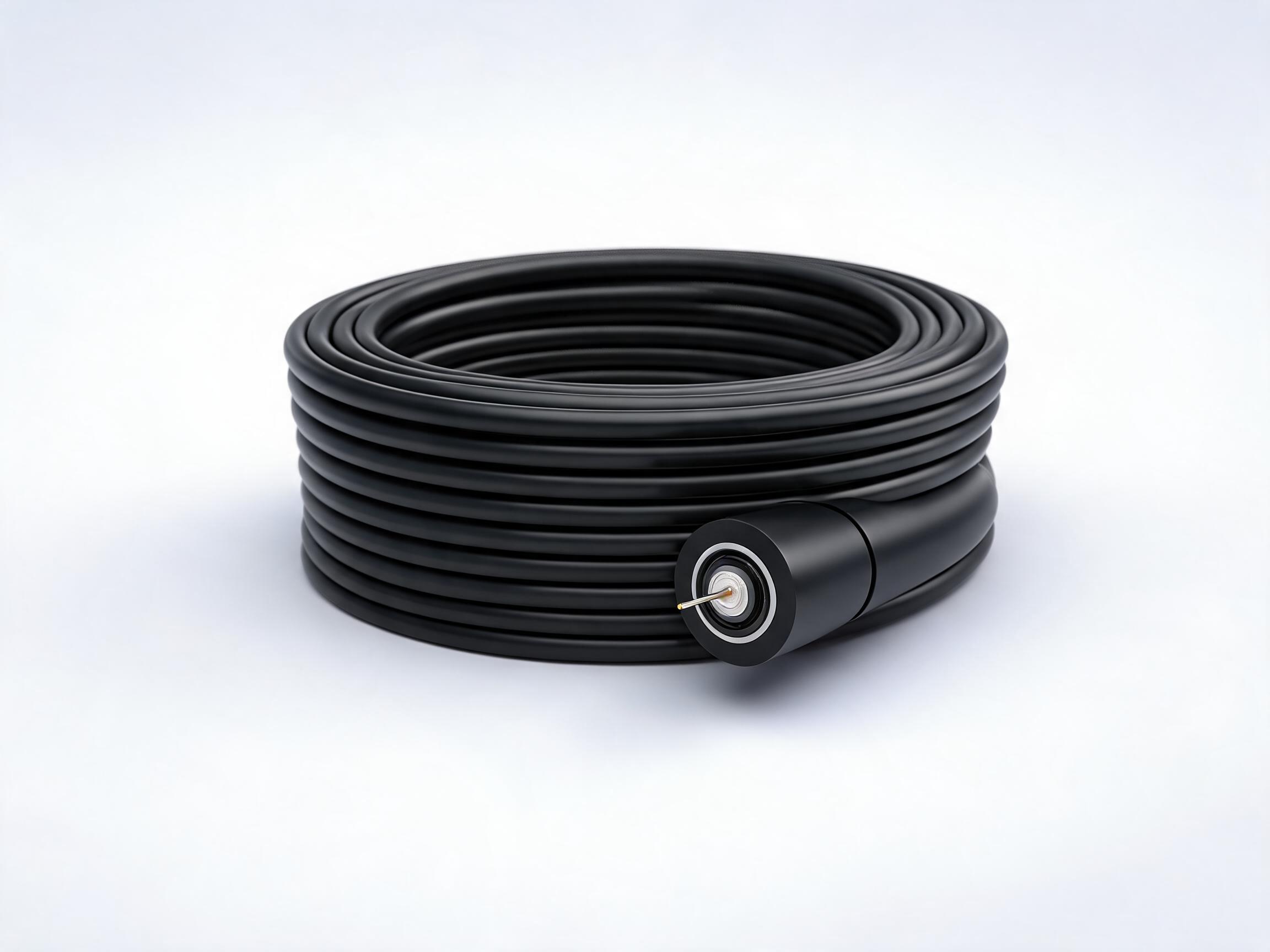
Outdoor Backbone: Loose-Tube G.652D Cable
For the inter-building backbone and long outdoor spans, a gel-filled loose-tube cable built on G.652D single mode fiber is the default choice. The loose-tube structure isolates the fibers from mechanical stress on the jacket and the gel blocks water migration — the failure mode that quietly degrades buried and duct routes over years. A typical outdoor construction covers 2 to 288 cores, handles operating temperatures from -40 °C to +70 °C, and is qualified for direct burial, duct and aerial deployment in the same family. Core count is the main sizing decision: count the fibers you need at each distribution point today, add spares for growth, and remember that re-pulling an outdoor backbone is the most expensive cable work on any site. The attenuation, mechanical and environmental figures for your ordered construction are stated on its datasheet and govern the final loss budget.
Outdoor G.652D Single Mode Fiber Optic Cable
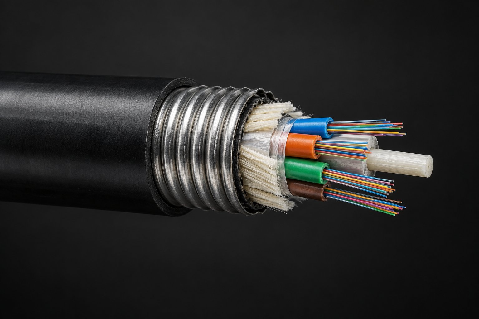
Harsh and Buried Routes: Armored Cable
Where the route has no duct protection, crosses yards and roadways, or runs through corridors where rodents gnaw buried cable, an armored construction adds a steel tape or steel wire layer between the core and the jacket. Steel tape armor is the standard choice for direct burial crush protection and a continuous rodent barrier; steel wire armor serves longer duct pulls and higher tensile demand. Typical armored constructions are specified up to 3,000 N/100 mm crush resistance with steel tape and up to 4,000 N/100 mm with steel wire, with short-term tensile ratings up to 3,000 N and 6,000 N respectively — typical values to be confirmed against the datasheet for the exact build. The buyer's guide to armored cable covers the armor-selection trade-offs in detail.
Armored Fiber Optic Cable · When Should You Use Armored Fiber Optic Cable? A Buyer's Guide
Inside the Plant: Tight-Buffered and Distribution Cable
From the building entrance to the control room, the network room and the plant-floor cabinets, tight-buffered indoor construction takes over. Each fiber carries its own 900 µm buffer, so installers can strip and terminate directly at patch panels without the loose-tube gel-cleaning steps, which matters on a site where most termination happens in live cabinets under time pressure. A typical indoor family covers 2 to 144 cores with riser (OFNR) or plenum (OFNP) fire ratings and LSZH or PVC jackets, so the rating can be matched to each building zone rather than averaged across the plant. For vertical drops and floor-level branching, a 2-to-48-core distribution cable in an LSZH jacket pulls as one unit and breaks out cleanly at the ODF or panel; LSZH matters in occupied spaces, control rooms and enclosed risers where smoke and halogen content are regulated.
Indoor Tight-Buffered Fiber Optic Cable · Distribution Fiber Optic Cable · What Is LSZH Fiber Optic Cable and When Should You Specify It?
| Route in the plant | Recommended construction | Why it fits |
|---|---|---|
| Control room ↔ remote buildings, campus backbone | Outdoor loose-tube G.652D, 12–96 cores typical | Long reach, water blocking, direct burial / duct / aerial in one family |
| Direct burial without duct, rodent-prone corridors | Armored, steel tape (or steel wire for heavy pulls) | Crush and rodent protection where the route has no conduit |
| Building entrance → network room → floor cabinets | Indoor tight-buffered, riser or plenum rating per zone | Fast direct termination at panels; fire rating matched per zone |
| Riser drops and floor-level branching | LSZH distribution cable, 2–48 cores | One pull replaces many; clean break-out at ODF and panels |
| Cabinet and switch cross-connects | Factory-terminated single mode patch cords | Measured insertion/return loss at delivery; no field termination |
The last row deserves a note because it is where industrial projects quietly lose performance. Field-terminated patch cords in the control room are the most common source of avoidable loss: polishing and inspecting connectors in a live cabinet rarely matches factory conditions. Factory-terminated cords — for example an SC-SC single mode G.652D assembly released with a per-cord insertion loss limit of ≤0.5 dB and return loss of ≥50 dB for UPC or ≥60 dB for APC end faces — arrive measured and dust-capped, which shortens commissioning and makes acceptance testing predictable. These figures are typical release limits for the product family; the datasheet for your order states the applied limits.
SC-SC Single Mode G.652D Patch Cord
Three Mistakes That Turn a Fiber Upgrade into a Rework Project
Between a sound design and a working network sit a handful of recurring mistakes. None of them is technical in nature; all of them are ordering and coordination errors that show up on site as rework.
Ordering by price per meter alone
The cheapest quote for a route is frequently the one that omits the details that matter: a construction rated for the actual installation method, test records with the shipment, or the spare drums that keep a damaged section from halting the pull. When comparing quotations, normalize them against the RFQ checklist above instead of the per-meter figure, and ask each supplier to state explicitly which datasheet values their acceptance test applies. A quotation that cannot name its datasheet is a quotation for a different cable than the one you specified.
Skipping the route walk
A route surveyed from drawings alone misses the realities that decide the pull: the tray that is already full above the welding line, the duct section that sags and collects water, the doorway where the bend radius has no room. One hour of walking the route with the installation crew converts directly into a realistic method statement — and into a cable construction that matches the route instead of one that matches the drawing. The pulling and bend-radius limits for the ordered construction then become planning inputs rather than surprises on installation day.
Treating termination as a site task by default
Every field termination is a small manufacturing process performed in a cabinet, often under schedule pressure, with results that vary by technician. Moving termination work to the factory — through pre-terminated backbone assemblies, factory patch cords and clearly labeled break-out points — removes the most variable step in the whole chain. The plant keeps the site work it is good at: pulling, mounting, connecting, and testing against numbers that were measured before the goods shipped.
Specification Checklist Before You Order
A fiber-versus-copper decision made without the specification details below is the most common origin of industrial cabling change orders. None of these items is difficult; all of them are cheaper to settle before the purchase order than after delivery.
- Route survey: measure actual path lengths, note tray and duct conditions, and mark every zone where the route runs near drives, welders or high-voltage equipment. This single sheet decides most of the fiber/copper split.
- Core count with growth margin: count today's fibers per route, add spares for the subsystems you know are coming, and size the cable once. Re-pulling an outdoor backbone costs multiples of the extra cores would have cost up front.
- Fiber type: single mode G.652D for backbone and anything beyond multimode's practical reach; OM3/OM4 multimode only where runs are short and transceiver economics favor it. Mixing types on one route forces media conversion — avoid it in the design phase.
- Fire rating per building zone: riser (OFNR) for vertical shafts, plenum (OFNP) for air-handling spaces, matched per zone rather than averaged; LSZH where smoke and halogen limits apply.
- Mechanical protection by segment: armored only where the route actually lacks protection; standard jacket where duct and tray already shield it. Over-specifying armor raises cost and bend-radius demands for no benefit.
- Connector polish end to end: confirm UPC or APC per port and order cords to match; a UPC-into-APC mating silently destroys return loss and surfaces as unexplained link errors months later.
- Bend radius and pulling limits: confirm the installation and in-service bend radii and tensile ratings for the ordered construction against your tray and duct layout before the pull is scheduled; the cable pulling guide covers field practice.
- Datasheet review: attenuation, environmental limits and warranty terms are typical-value statements until the datasheet for your specific build is issued with the order — review it as part of the RFQ, not after delivery.
How Do You Pull Fiber Optic Cable Without Exceeding Tension and Bend Limits? · What Information Should You Include in a Fiber Optic Cable RFQ?
Migration Strategy: Running Fiber and Copper Together
Almost no industrial site converts to fiber in one project, and none needs to. The standard migration pattern converts routes in order of risk, keeping both media in service for years:
Phase one — the backbone. Convert inter-building and long intra-site routes first. They carry the most traffic, trip the distance and noise triggers most reliably, and their failure affects the most subsystems. This is also the phase with the best cost logic, because the active equipment removed from intermediate cabinets offsets a meaningful share of the cable cost.
Phase two — noisy zones. Convert the segments that have produced documented EMI symptoms: the drive bay, the welding line, the substation feed. These conversions are usually small in length and pay back in eliminated troubleshooting rather than in bandwidth.
Phase three — the edge stays copper. Device connections within 100 meters of a local switch, especially PoE-powered cameras and access points, normally stay copper indefinitely. The goal of the migration is a fiber backbone with copper at the edges — not the elimination of copper.
During the transition, media converters bridge the two worlds at defined points. Use them deliberately and record them: each converter is a powered device with its own failure modes, and an undocumented converter is the classic source of "mystery" link problems during an upgrade program. Budget the converter fleet, label it, and retire it as the copper routes it serves are converted.
Quality, Testing and Warranty Expectations
Whatever the media split, the acceptance discipline is the same and should be agreed before the order. For fiber routes, every link is tested for insertion loss with a light source and power meter — and on backbone routes, an OTDR trace documents splice quality and locates future faults to within meters. For cords and cross-connects, insist on factory test records or per-cord release limits so incoming inspection has numbers to compare rather than impressions. The acceptance figures come from the datasheets supplied with the delivered reels and assemblies; quoting them in the RFQ is what makes them enforceable.
Warranty terms belong in the same conversation. Nexora supplies its fiber optic cables and patch cords with a 12-month warranty from shipment date covering manufacturing defects, with claims handled against the reel label and delivery documents. Confirm the warranty scope for each line item when you request the quotation, and note that installation damage — bends beyond the rated radius, tension beyond the rated load, third-party civil work — sits outside the manufacturing-defect scope on every cable brand, which is one more reason the installation disciplines above matter. For a fuller walkthrough of what the warranty period does and does not cover, see the dedicated warranty guide.
What Does a 12-Month Warranty Really Cover for Fiber Optic Buyers?
Reputable manufacturers back these terms with documented quality control. When you evaluate a supplier, the questions that separate a real manufacturer from a trader are concrete: how many QC stations run across incoming material, in-process and final inspection; whether attenuation is measured on the finished reel before packing; whether test records can ship with the goods; and whether custom constructions — non-standard core counts, jacket materials, drum lengths or printed markings — are produced in-house. A manufacturer running its own lines can answer each of these from process documents rather than assurances.
Frequently Asked Questions
Is fiber optic cable more expensive than copper overall?
Per meter of material, yes at short lengths. On installed cost, the ranking depends on the route: beyond 100 meters, between buildings, or across electrically noisy zones, fiber typically wins because it removes intermediate switches, surge protection and recurring troubleshooting. On short, quiet edge runs, copper remains the cheaper and perfectly adequate answer.
Can I mix fiber and copper on the same network?
Yes, and it is the standard design: fiber for the backbone and long or noisy routes, copper with local switching and PoE at the edges. Media converters or fiber-equipped switches bridge the two; document every conversion point.
Does fiber really not care about electromagnetic interference?
The optical path does not: light in glass cannot be disturbed by external fields. Two caveats apply — metallic elements in the cable (steel armor, metal strength members) should be considered when routing near high-voltage equipment, and the electronics at each end still need ordinary EMI hygiene. All-dielectric constructions remove the metallic elements where that matters.
What distance can a fiber optic cable cover?
Far beyond any industrial need when properly budgeted. With typical single mode attenuation of ≤0.36 dB/km at 1310 nm and ≤0.22 dB/km at 1550 nm (typical values — confirm the datasheet for your reel), multi-kilometer spans fit comfortably inside standard transceiver power budgets. Work the route through a link budget calculation rather than assuming a maximum distance.
Who installs and terminates fiber — do we need specialists?
Fusion splicing and field termination require trained crews and equipment, and many plants outsource them. The requirement shrinks as factory-terminated products expand: pre-terminated backbone assemblies and factory patch cords move most termination work from the field to the production line, so site work becomes pulling, mounting and plugging in.
How do I decide core count for an industrial backbone?
Count the fibers each distribution point needs today, add spares for known future subsystems, and size once. On a typical plant, 12–48 cores covers the backbone with margin; larger campuses and utility routes commonly order 96 or more. The re-pull cost of an undersized backbone always exceeds the price of the spare cores.
What should I confirm before ordering?
Route lengths and environment, core count, fiber type, fire rating per zone, jacket material, armor requirement per segment, connector polish, bend and tensile limits against your tray layout, and the datasheet values that your acceptance test will check. Putting these items in the RFQ converts them from assumptions into enforceable specifications.
The Bottom Line for Industrial Buyers
The fiber-versus-copper decision is not a referendum on the two technologies; it is a route-by-route allocation. Copper remains the right medium at the network edge — short, powered, well-behaved segments within 100 meters of a switch. Fiber optic cable is the right medium for everything the edge connects to: the backbone, the inter-building links, the runs through noisy electrical environments, and any route where failure takes down multiple systems at once. Specified with the correct construction for each segment — outdoor loose-tube for the campus backbone, armored where the route lacks protection, tight-buffered and distribution cable inside the plant, factory-terminated cords at the cross-connects — and ordered with the datasheet, test records and warranty terms written into the RFQ, the fiber portion of an industrial network is a one-time investment that outlasts several generations of the equipment attached to it.
When you are ready to price the fiber portion of your project, send the route survey: path lengths, environments per segment, core counts and connector requirements. A manufacturer-side review of those details returns a configuration and a quotation built around the routes you actually have — not around a generic product list.